Facebook
 Google
 GitHub
 Linkedin
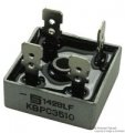
i have 1000v 10 amp bridge rectifier, what is 10 amp & 1000v means
Is it 10 amp is max current it give & is it 1000v constant voltage ?????
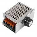
i have ac potentiometer, may i use it after bridge rectifier - dc voltage ????
may control dc voltage with potentiometer ????
help me sir...
Is it 10 amp is max current it give & is it 1000v constant voltage ?????
i have ac potentiometer, may i use it after bridge rectifier - dc voltage ????
may control dc voltage with potentiometer ????
help me sir...