[SOLVED]Relay board to control light bulb

Thread Starter

Djsarakar

Joined Jul 26, 2020
489
Hi
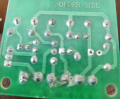
I've got a relay board in my store room I think it may be use to control any ac devices (light bulb ). Module work on 12v DC

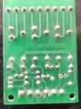
I have attached picture of top and bottom side

I am looking help to connect this module with AC bulb.

Any help would be highly appreciated
 

Attachments

jpanhalt

Joined Jan 18, 2008
11,087
The top apparently is just the 9 contacts (NC, COM, NO) brought out to a connector.
1604061479557.png

The relay coils are 12V DC, and the lower half of the board seems related to that. I don't see any diodes in the fuzzy picture, so I assume the control signals are DC.

I don't see anything that would restrict the device to controlling only AC lamps. There is no obvious voltage rating for the contacts. Whatever device(s) that are controlled would have their own power and must be within the allowed specifications for the contacts.

With a clearer picture of the lower half, you should be able to draw its schematic. From that, one might be able to figure out how it works.
 

Dodgydave

Joined Jun 22, 2012
11,284
Three Changeover contacts , and two relays are straight input DC Negative pulse, they all have back EMF diodes Common Positive, one relay is triggered by a transistor.
 

MaxHeadRoom

Joined Jul 18, 2013
28,617
You will need to observe polarity when you connect the two input pins for each relay coil, the +ve power connection will connect to the stripe on the end of the rectifier diodes just below the relays.
Two indicator LED's appear to be missing?
Relays are made by O/E/N India Limited.
Max.
 
Last edited:

Thread Starter

Djsarakar

Joined Jul 26, 2020
489
With a clearer picture of the lower half, you should be able to draw its schematic. From that, one might be able to figure out how it works.
I am not good at reading layout but I have tried my best to understand and I have drawn following diagram that should be match lower half of module. I have doubt with second and third relay connection

1604142569321.png
 

Attachments

jpanhalt

Joined Jan 18, 2008
11,087
Grounding Pin2 should turn on LED1 and operate the associated relay. For the middle relay, this connection might make more sense:
1604143139136.png

Then it will operate like the leftmost relay.

As for the right hand relay, that appears to be controlled by an NPN transistor (BD139). It appears that a voltage on Pin4 while Pin5 is grounded is intended to operate it.
1604143701658.png
However , the connection marked with red doesn't make sense. It provides a permanent ground to the base of the transistor , which will keep it from ever turning on. I suspect the two resistors from Pin4 to the Base are intended as a voltage divider. Maybe the 5k is connected to ground and the junction between the 10k and 5k goes to the base. There are other options. Double check those connections.

EDIT:
I missed this short:
1604145348370.png

If changed, then it would be wired analogously to the other relays.
 
Last edited:

jpanhalt

Joined Jan 18, 2008
11,087
That should operate the relays and LED's with appropriate inputs to pins 2, 3, and 4. For pins 2 and 3, the input consists of grounding the pin to turn the LED on and close the NO contact. For pin 4, one would need to apply a small voltage to pin 4 while pin 5 was grounded or visa versa.

Whether that is a how the PCB is actually wired is another question.
 

hexreader

Joined Apr 16, 2011
581
@Djsaraker (or it it Djsarker ? - you use both)

Measuring resistor values in-circuit is not a valid thing to do

You were lucky with this circuit that you came fairly close, but it will not always work

Read the resistor colour code in future

Google "E12 series resistors" and you will find standard values. 5 is NOT a standard value, 4.7 IS.
 
Last edited:

Thread Starter

Djsarakar

Joined Jul 26, 2020
489
okay I have disordered one relay from the board

Please look at circuit in picture if connection looks correct then I am going to try this circuit on breadboard

1604233896777.png
 
Top