Facebook
 Google
 GitHub
 Linkedin
MisterBill2
- Joined Jan 23, 2018
- 27,841
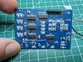
The problem with the counter that does not reset is that internally the reset pulse is too short, but with theother 4017 the pulse is longer. The two devices are different brands I suspect. I have run into this problem before, that different brands of the same part number are just a bit different. And the timing between the output going zHigh and the reset action happening is not specified.
A cheap trick could be a diode OR of outputs 4 and 5 to do the full reset to zero.
A cheap trick could be a diode OR of outputs 4 and 5 to do the full reset to zero.