[SOLVED] Binary counter not working

Thread Starter

enjoykilian

Joined May 15, 2021
95
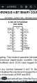
Hello I am making a 16 bit up counter with a sn74f163an ic but if the first ic reaches 15 then the next ic shows 1 0001 but sometimes the first ic will go from 15 1111 to 1 0001 and sometimes to 0 0000

Why does it go to 1 0001 sometimes
 

Boggart

Joined Jan 31, 2022
82
It's been a long time since I've used them, but I seem to recall 74 series chips need good decoupling, make sure there's at least a 100nF cap across the supply rails of each IC, close to the device.
 

Thread Starter

enjoykilian

Joined May 15, 2021
95
I can't acces a computer right now so i can't make the schematic
I can trie to explain it the rco of the first ic is connected to the enp and ent of the next chip so is it with the second and third and fourth the clock is connected to all four ic in the clock pin and the inputs are currently nc the outputs go to the leds load pin is high on all four so is clear
 

Attachments

dl324

Joined Mar 30, 2015
16,846
I can trie to explain it the rco of the first ic is connected to the enp and ent of the next chip so is it with the second and third and fourth the clock is connected to all four ic in the clock pin and the inputs are currently nc the outputs go to the leds load pin is high on all four so is clear
It would be best to wait until you can make a schematic. One of the enable inputs is to enabling carry out, so it can be tied HIGH unless your intent is for carry to only be enabled when counting is enabled.
 

Papabravo

Joined Feb 24, 2006
21,159
Here is a simulation using the 74HC163 counter which is functionally the same as the 'F' series part. Everything on this counter is synchronous including load and RESET. The counter counts up from 0. The Full Adders subtract each positive counter value from 0 making a down counter. This is then converted to an analog value with an R-2R ladder network.
1659111959207.png
CEP & CET are both enabled on the lowest order stage. TC on the lowest stage controls CET on the next stage. Wash, rinse, repeat for the following stages to build a bigger counter. This will get the counters counting. If you want to do more complicated things like loading the counters or resetting the counter, then your logic for controlling CET & CEP needs to change
 
Last edited:

dl324

Joined Mar 30, 2015
16,846
I can trie to explain it the rco of the first ic is connected to the enp and ent of the next chip so is it with the second and third and fourth the clock is connected to all four ic in the clock pin and the inputs are currently nc the outputs go to the leds load pin is high on all four so is clear
Something like this?
1659114756377.png
 

Thread Starter

enjoykilian

Joined May 15, 2021
95
Here is a simulation using the 74HC163 counter which is functionally the same as the 'F' series part. Everything on this counter is synchronous including load and RESET. The counter counts up from 0. The Full Adders subtract each positive counter value from 0 making a down counter. This is then converted to an analog value with an R-2R ladder network.
View attachment 272508
CEP & CET are both enabled on the lowest order stage. TC on the lowest stage controls CET on the next stage. Wash, rinse, repeat for the following stages to build a bigger counter. This will get the counters counting. If you want to do more complicated things like loading the counters or resetting the counter, then your logic for controlling CET & CEP needs to change
Thats the circuit i use but it doesn't work
I figured out that it goes from xx7F to xx81
Or from xxFF to xx01 for all other cases (xxxF) it goes to xxx0
 

Papabravo

Joined Feb 24, 2006
21,159
Thats the circuit i use but it doesn't work
I figured out that it goes from xx7F to xx81
Or from xxFF to xx01 for all other cases (xxxF) it goes to xxx0
Have you eliminated the possibility of a wiring mistake or the possibility of miscounting because of switching transients when the counters roll over. Also you need to check to see if there are setup or hold time violations. Don't forget that with F-series parts you need adequate bypassing and super solid ground connections, especially on bread boards.
 

Thread Starter

enjoykilian

Joined May 15, 2021
95
Have you eliminated the possibility of a wiring mistake or the possibility of miscounting because of switching transients when the counters roll over. Also you need to check to see if there are setup or hold time violations. Don't forget that with F-series parts you need adequate bypassing and super solid ground connections, especially on bread boards.
I rewired it for about 5 times now same error it is also not the clock because it is always on the same count it goes to 1 i also switched to different 74f163an and everything is properly grounded it is strange it does it at specific counts
I will check wiring again
 

Papabravo

Joined Feb 24, 2006
21,159
I rewired it for about 5 times now same error it is also not the clock because it is always on the same count it goes to 1 i also switched to different 74f163an and everything is properly grounded it is strange it does it at specific counts
I will check wiring again
In both cases that you mentioned the counter is rolling over from 1's to 0, then a single 1. Something is causing this that you may have overlooked. Even 1 V of ground bounce can cause multiple triggering. These parts really need a printed circuit board. Failing that you can try debugging the connections at a slower speed.

I have to ask about how you're constructing these circuits.
 
Top