[SOLVED] 0 To 9 Digital Counter

Thread Starter

aac044210

Joined Nov 19, 2019
178
Hi:

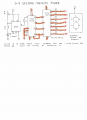
I built the attached 0 to 9 digital counter. For now I left the 555 timer out. When I power up the circuit, it displays a "9". Is that
to be expected? When I momentarily apply +5 volts to pin 14 of the 74LS90, I expected the number on the display to change?

I should have used a 4026 and a common cathode display but I don't have any cmos devices at this point.

Please advise. Thanks.

aac044210_counter_cropped.png
 

Attachments

Last edited by a moderator:

Thread Starter

aac044210

Joined Nov 19, 2019
178
Yes. If you want it to power up with a certain count, you need to include circuitry to do that.
You should also not leave inputs floating.
Thanks Dennis. I am now applying a 1Hz, 5 volt p-p square wave to pin 14 of the 74LS90. The display
shows "1" then "9" over and over. Any ideas as to what I have done wrong? The count must be
inhibited some how.
 
Last edited:

dl324

Joined Mar 30, 2015
16,845
I am now applying a 1Hz, 5 volt p-p square wave to pin 14 of the 74LS90. The display
shows "1" then "9" over and over. Any ideas as to what I have done wrong? The count must be
inhibited some how.
You either have a wiring error or a bad chip. Post a picture of your breadboard.
 

djsfantasi

Joined Apr 11, 2010
9,156
What are pins 3, 4, 5 on the 7447 connected to?

They must be connected to something or it’s operation will not be predictable.

Do you have any unconnected pins on your 555 or 7490?
 

Thread Starter

aac044210

Joined Nov 19, 2019
178
What are pins 3, 4, 5 on the 7447 connected to?

They must be connected to something or it’s operation will not be predictable.

Do you have any unconnected pins on your 555 or 7490?
Hi:

I guess the original Mims circuit is wrong, pins 3,4,5 were not connected to anything. I have now connected them to +5 Volts.
The only pin on the 74LS90 is #13. All 555 pins are connected to something. I am now using this schematic but the signal
is from a 555 rather than a single pulse from a push button. I am still just getting a "9" on the display.

1604523111759.png
 

djsfantasi

Joined Apr 11, 2010
9,156
I do not have a cell phone.
And I suppose your computer doesn’t have a camera as well...

Nor do you have a multipurpose printer...

And there is no store near you that can scan your circuit...

And none of your family or friends have a cell phone either (which they can use to take a pic and email it to you)...

There may be other options that you don’t have...

You may be out of luck!

I’m just trying to help you “think out of the box”.
 

dl324

Joined Mar 30, 2015
16,845
Pins 6 & 7 on the 74LS90? It is 1.4 volts.
Your schematic shows them connected to ground. Anything above 0.8V is treated as logic HIGH. That's why you just see 9's.

Earlier you said you were seeing the display alternate between 0 and 9. Check the reset to 0 inputs to make sure they're also grounded.
 

dl324

Joined Mar 30, 2015
16,845
Issue was a missing ground connection.
The next time you have a problem, don't trust just a visual check for your wiring. I've had breadboard wires snap off at the ends because I nicked the wires. When a visual check doesn't yield any results, I use standard troubleshooting techniques (measure and verify) and that always works.
 

Thread Starter

aac044210

Joined Nov 19, 2019
178
The next time you have a problem, don't trust just a visual check for your wiring. I've had breadboard wires snap off at the ends because I nicked the wires. When a visual check doesn't yield any results, I use standard troubleshooting techniques (measure and verify) and that always works.
Thanks. That is good advice.
 
Top