Facebook
 Google
 GitHub
 Linkedin
This Pot is driving me nuts! I have no Idea why its not working as it should, I followed what the data sheet said: Set CS (Chip Select) LOW, Set UD (Up/Down) direction, Trigger INC LOW then HIGH. then set CS HIGH to write to EEPROM or set CS HIGH before setting INC HIGH to not write to EEPROM.
This DOES work properly! However, only if I write to EEPROM right after by setting CS HIGH again.
Since I dont want to write to EEPROM, I chose to leave CS LOW all the time, for now. It does work, using the osc-scope I can see the voltage varies UP/DOWN but not within the correct range, given an analog voltage of 1.5 and Wiper is set to 1, the analog output voltage is around 1V ?!.
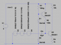
X9C103 connections:
CS, U/D, INC to Arduino digital IO pins
VH (High Terminal) to analog input
VL (Low Terminal) to GND
VW (Wiper) as output
Any advice/help is much appreciated. Thanks in advance.
Datasheet: http://pdf1.alldatasheet.com/datasheet-pdf/view/34250/XICOR/X9C103P.html
This DOES work properly! However, only if I write to EEPROM right after by setting CS HIGH again.
Since I dont want to write to EEPROM, I chose to leave CS LOW all the time, for now. It does work, using the osc-scope I can see the voltage varies UP/DOWN but not within the correct range, given an analog voltage of 1.5 and Wiper is set to 1, the analog output voltage is around 1V ?!.
X9C103 connections:
CS, U/D, INC to Arduino digital IO pins
VH (High Terminal) to analog input
VL (Low Terminal) to GND
VW (Wiper) as output
Any advice/help is much appreciated. Thanks in advance.
Datasheet: http://pdf1.alldatasheet.com/datasheet-pdf/view/34250/XICOR/X9C103P.html
Code:
//-----------------------------------------------------------------------
// DPX9C Digital Pot
//-----------------------------------------------------------------------
// Arduino Uno pin 10 to X9Cxxx increment pin (INC) - 1
// Arduino Uno pin 09 to X9Cxxx up/down pin (U/D) - 2
// Arduino Uno pin 08 to X9Cxxx CS pin (CS) - 7
// ---Constants---
const byte DPX9C_INC = B00000100;
const byte DPX9C_UD = B00000010;
const byte DPX9C_CS = B00000001;
const byte DPX9C_POWERUP_TIME = 50;
const byte DPX9C_CS_TIME = 20;
const byte DPX9C_INC_TIME = 1;
// DPX9C Maximun number of steps
const byte DPX9C_STEPS = 100;
const byte DPX9C_LOWER_LIMIT = 1;
const byte DPX9C_UPPER_LIMIT = DPX9C_STEPS - DPX9C_LOWER_LIMIT;
byte volatile dpWiper;

static inline void dpDecrease()
{
  if (dpWiper > DPX9C_LOWER_LIMIT)
  {
    dpWiper--;
    PORTB &= ~DPX9C_UD;
    PORTB &= ~DPX9C_INC;
    delayMicroseconds(DPX9C_INC_TIME);
    PORTB |= DPX9C_INC;
  }
}

static inline void dpIncrease()
{
  if (dpWiper < DPX9C_UPPER_LIMIT)
  {
    dpWiper++;
    PORTB |= DPX9C_UD;
    PORTB &= ~DPX9C_INC;
    delayMicroseconds(DPX9C_INC_TIME);
    PORTB |= DPX9C_INC;
  }
}

void setupDP()
{
  // Wait for DPX9C to complete its powerup sequence
  delay(DPX9C_POWERUP_TIME);
  PORTB &= ~DPX9C_CS;
  PORTB |= DPX9C_INC;
  // Set the digital pot all the way down to zero;
  dpWiper = DPX9C_STEPS << 1;
  while (dpWiper > DPX9C_LOWER_LIMIT)
    dpDecrease();
  while (dpWiper < DPX9C_UPPER_LIMIT)
    dpIncrease();
}
Last edited: