Facebook
 Google
 GitHub
 Linkedin
hi,
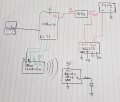
I would say 10W at 17V, ie: 10W/17V = 0.58A
A 30R 10Watt load resistor at max output.
Look thru this PDF
E
https://www.altestore.com/blog/2016/04/how-do-i-read-specifications-of-my-solar-panel/#.XAKBurg6DgI
I would say 10W at 17V, ie: 10W/17V = 0.58A
A 30R 10Watt load resistor at max output.
Look thru this PDF
E
https://www.altestore.com/blog/2016/04/how-do-i-read-specifications-of-my-solar-panel/#.XAKBurg6DgI
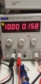
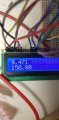
 if it is measuring voltage across Vin- and GND why is it displaying different voltage