Yes I have just measured the voltage drop across shunt resistor and I can confirm that it is 4.2mV with the current 42mA which makes sense. But where is 0.1V dissapearing then?
hi,
OK,
My next step would be use a DVM to confirm that the Voltage at the +Vin is what the the power supply meter states, do they agree.?
How are you measuring/determining that there is a 0.1V difference.?
With the power supply set to +5V, Vin+ measures 4.98V . I am determining the difference between the voltage by displaying the voltage reading on my LCD display. I am just priting load voltage and I expect it to match the supply voltage but it does not as I mentioned before
// initialize the library by associating any needed LCD interface pin
// with the arduino pin number it is connected to
const int rs = 12, en = 11, d4 = 5, d5 = 4, d6 = 3, d7 = 2;
LiquidCrystal lcd(rs, en, d4, d5, d6, d7);
void setup(void)
{
Serial.begin(9600);
while (!Serial) {
// will pause Zero, Leonardo, etc until serial console opens
delay(1);
}
uint32_t currentFrequency;
Serial.println("Hello!");
// Initialize the INA219.
// By default the initialization will use the largest range (32V, 2A). However
// you can call a setCalibration function to change this range (see comments).
ina219.begin();
// To use a slightly lower 32V, 1A range (higher precision on amps):
//ina219.setCalibration_32V_1A();
// Or to use a lower 16V, 400mA range (higher precision on volts and amps):
//ina219.setCalibration_16V_400mA();
Serial.println("Measuring voltage and current with INA219 ...");
}
Hi Eric,
I have just done a test to see how my INA219 compares with my Fluke 114 & Fluke175 meters. Just some information on the setup. The INA219 is on the output of a battery charger. The charger is connected to a 12 volt SLA battery but there is no mains to the charger. There will be no leakage current back into the charger as there is a relay that only connects it to the battery when there is mains input to the charger.
Both Fluke meters read 11.98 volts.
The - 0.0252 amps will be the current taken by the INA219
As you can see the reading is only 0.008 volts less than the Flukes which is as close as can be expected if you consider That the last digit can always be + or - 1 count.
Just for interest This is using a PIC12F1840 to read the INA219 and convert it to the text in the screen capture from "Tera Term" (Terminal emulator.) This is transfered via 2 HC-12 RF modules. I just sent the characters #E to request the reading. (If I send #C I get the temperature and humidity from another sensor in my workshop that uses a DHT22 sensor, a PIC12F1840 and another HC-12
Still havent figured out the 0.1 V error but I have another question. Is it possible to measure solar battery voltage and current whilst powering the circuit wih external power supply instead of using solar panel as a supply. I did try to connect my solar panel as a load ( I have connected positive terminal of power supply to Vin- of the INA219 and Vin+ of INA219 to positive terminal of power supply, but it did not work- the readings i get is 0V and 0 current. How would I connect to measure the charge of battery?
I have made such connection and I think it would make sense if I connect Vin+ to the solar panel istead of my battery. Although I have realised that there is really no point to measure that because if I power my circuit from the battery, there will be no current drawn from the solar panel even if its very sunny. I have just wanted to consider the emergency scenario where I would power the system with external supply instead of solar battery if the sun dissapear to keep the system running for a while.
hi,
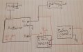
You posted if I connect Vin+ to the solar panel, but your sketch showed Vin- to the panel. [ I have corrected it]
If your panel does not have a reverse current blocking diode, you should add a diode, ref this image.
If the solar panel voltage output plus diode drop, is higher than the battery voltage, the panel should power the logic and charge the battery.
The INA219 module should measure a positive current from the panel.
The sketch does not show any circuitry for solar to battery charging control.??
Because I am not using any charge controller or battery that can be charged. The idea was to run the system with solar panel as a supply, but have the emergency 9v battery that can power the system if required. Ideally I would like to charge a battery with a solar panel and run the system through the battery instead of running it straight from solar panel because then I would be able to measure how much power is stored in that battery instead of measuring instantenious values but I was not able to find an easy and cheap aproach.
But with this connection I have shown i get 0v and 0A readings, so maybe I should connect Vin+ to the solar panel instead of battery. Thats what i meant .Would that make a difference ?
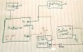
This image shows how to run the logic from the 9v battery, until the solar panel output is higher than the battery voltage.
The panel will then power the logic.
But with this connection I have shown i get 0v and 0A readings, so maybe I should connect Vin+ to the solar panel instead of battery. Thats what i meant .Would that make a difference ?
I did measure it few days ago. I got 21.6V open circuit. Il try doing connecting it to the circuit outside rather then indoors today and see what I get
 Facebook
 Google
 GitHub
 Linkedin