Solar panel current measurement using INA219

Thread Starter

zazas321

Joined Nov 29, 2015
936
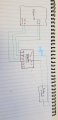
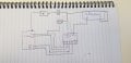
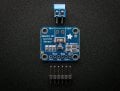
Hello. I am working on my project and I need to measure solar panel current. I am able to measure voltage of the solar panel by using potential divider and connecting to analog pin of the arduino and then reading the pin. I also need to measure a current up to 1A and I have found a chip INA219. But i do not know how to properly connect this chip to my system. https://www.adafruit.com/product/904
I want to connect the current sensor to the positive terminal of my solar panel ( high side ) and display the current and voltage readings on my LCD display. Could someone give me some tips? Thanks

MOD: Rotated your image.
46708209_343779539719206_6805908849162190848_n.jpg
 
Last edited by a moderator:
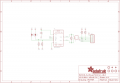
Thread Starter

zazas321

Joined Nov 29, 2015
936
I had a look at INA219 board from adafruit that has a shunt resistor built in already so thats why I am a little bit confused. I have added few pictures that I have managed to get from adafruit website. Lets say i cannot Vcc to positive terminal of my solar panel and GND to negative terminal of my battery, what is Vin+ and Vin- used for then? and where do i connect my output ( voltage regulators) and where do I measure my current?
 

Attachments

bertus

Joined Apr 5, 2008
22,270
Hello,

Did you read this piece on the product page?
It descibes the value and use of the shunt resistor:

A precision amplifier measures the voltage across the 0.1 ohm, 1% sense resistor. Since the amplifier maximum input difference is ±320mV this means it can measure up to ±3.2 Amps. With the internal 12 bit ADC, the resolution at ±3.2A range is 0.8mA. With the internal gain set at the minimum of div8, the max current is ±400mA and the resolution is 0.1mA. Advanced hackers can remove the 0.1 ohm current sense resistor and replace it with their own to change the range (say a 0.01 ohm to measure up 32 Amps with a resolution of 8mA)

Bertus
 

Thread Starter

zazas321

Joined Nov 29, 2015
936
Yes I have read that I will not get anywhere close to 3.2A. My solar panel can reach 0.5-0.6A so 1A is more than enough for me. I could not find any other current sensing chips that would be more suitable
 

ericgibbs

Joined Jan 29, 2010
18,766
hi,
If I understand you correctly, this is how I would connect it, ref images.
If in doubt please ask.
E

NOTE: Vin [ bottom right] maybe connected on the PCB, if not link as shown in the circuit diagram

AA1 22-Nov-18 12.51.gif
AA1 22-Nov-18 12.47.gif
 
Last edited:

bertus

Joined Apr 5, 2008
22,270
Hello,

When you do not go over 0.8 A , you can reduce the gain of the INA219.
See the datasheet how to change the gain.

Bertus
 

Attachments

Thread Starter

zazas321

Joined Nov 29, 2015
936
hi,
If I understand you correctly, this is how I would connect it, ref images.
If in doubt please ask.
E

NOTE: Vin [ bottom right] maybe connected on the PCB, if not link as shown in the circuit diagram

View attachment 164234
View attachment 164236
It would be easier for me to understand if you draw on the INA219 adafruit chip instead of INA219 individual chip because the one on adafruit have some additional things added. I am adding one more picture so you can understand what exactly I mean.
In the first picture, according to this website:http://henrysbench.capnfatz.com/hen...urrent-sensor-voltmeter-tutorial-quick-start/ , i should be able to measure the current and voltage of my solar panel. But If i want to further connect voltage regulators to my solar panel , is it correct to connect them like that? ( See second picture).
 

Attachments

Thread Starter

zazas321

Joined Nov 29, 2015
936
Okay and this is exactly what I am confused about. I am not sure what to do with my LOAD because it is way more complicated than LED. I connect two voltage regulators to my solar panel that further connect to more devices and I do not know where do I connect Vin -. So according to your sketch, instead of led and resistor, I use 5V and 3.3V regulators as my load.

Also, I am a little bit confused why positive terminal of LED leg is connected to Vin- ?
 

Attachments

ericgibbs

Joined Jan 29, 2010
18,766
hi,
I would say the printed ident labels on those pins are misleading.

Vin is the connection to the solar panel and -Vin is out to the load.
To measure the current from the solar panel to the load [ on the high side] the current must flow thru that sense resistor.

I have shown the LED from the link circuit to show how the load is connected.

The load can be your voltage regulator inputs or a rechargeable battery etc ...

Look at the Fig 19 I posted you can see the load current drawn by the load from the solar panel flows thru that resistor. OK.

AA1 22-Nov-18 13.22.gif
 

Thread Starter

zazas321

Joined Nov 29, 2015
936
Okay, so could I connect my Vin- of current sensing chip as shown in the picture below? It would be probably easier to experiment and test myself. I am currently waiting for my components to arrive. Thank you for your help anyways!
 

Attachments

ericgibbs

Joined Jan 29, 2010
18,766
hi 321,
Please post a decent drawing showing more detail on how the solar/INA/ regulators are going to be connected, so that we can be sure its correct.
E
 

LesJones

Joined Jan 8, 2017
4,174
I have used the same type of INA219 module for monitoring battery charging voltage and current. I Added 3 extra 0.1 ohm resistors in parallel the onboard 0.1 ohm current shunt to get the current range I required. (So my shunt value was now 0.025 ohms.) I use a PIC12F1840 to read the data and convert into readable ASCII text . This is then transmitted to a PC using a pair of HC-12 RF modules. At the moment I just display the results using "Tera Term" terminal emulator program. If it is any help to you I can post the code that runs on the PIC12F1840.

Les.
 

Thread Starter

zazas321

Joined Nov 29, 2015
936
Hey. I have finally received my INA219 chip and I am just trying to do a simple excersise to display the current and voltage of my power supply. I have added pictures and I cannot understand why there is a difference of about 0.1V between my power supply and INA219 reading. I have tried a range of voltages and it seems to increase with increased supply voltage. Does anyone know why is it happening? I am aware that there is 0.1 Ohm resistor on INA219 chip, but with the current flow of 40mA, the voltage drop should be only 4mV . Am I right?
 

Attachments

Top