
I have already worked on it but I can't seem to make it precisely as it should be.
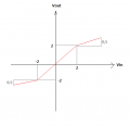
So the problem asks to create a circuit according to the transfer characteristic of the soft limiter shown in the figure below (blah).
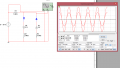
I managed to create a circuit (blah2) but it doesn't work because I need Vo=1/2Vi for -30<Vi<-2 and Vo=Vi for -2<Vi<2 and Vo=1/2 Vi for 2<Vi<30 ....but I only get 1/2 Vi +- 1/2 2V
So if anyone can help I would be very grateful...
So the problem asks to create a circuit according to the transfer characteristic of the soft limiter shown in the figure below (blah).
I managed to create a circuit (blah2) but it doesn't work because I need Vo=1/2Vi for -30<Vi<-2 and Vo=Vi for -2<Vi<2 and Vo=1/2 Vi for 2<Vi<30 ....but I only get 1/2 Vi +- 1/2 2V
So if anyone can help I would be very grateful...
Attachments
-
 4.4 KB Views: 11
 -
 39.9 KB Views: 13
")


