SMPS with UC3845

Thread Starter

agsuresh

Joined Dec 28, 2023
66
I made a simple smps with uc3845. The output of the ic is connected to IRF840 and a EE30_15_7 ferrite transformer wound by me. The osc section seems to be working.

Vcc supplied is 16.5 v

Pin 1 connected to opto coupler

pin 2 to GND

Pin 3 to the 0.47ohm resister connected between Mosfet Source and GND

pin 4 to 10 nf cap to GND

pin 5 to GND

pin 6 to a 47 ohm resister connected to gate of mosfet

pin 7 to VCC 16.5 volt

Pin 8 to 10K multiturn pot to pin 4

Snubber circuit

Diode - Resister + 1nf capacitor connected between the primary windings.

I tried winding data calculated by the formula Np= Nv *10^8 / 4 * Bmax * Freq * Ae

Bmax was taken as 1650

Ae = core size in cm2

Secondary should get 13v as per winding data.

The supply was given through a 60 w filament bulb.

It lights up when switch on. If the turn the pot and increase the frequency more than 125khz ( using a arduino uno ) , the light dims. However the output is only less 1 volt. At 50khz the bulb lightup like a virtual short circuit.

I tried changing the turns and even the core. Nothing seems to work. Any idea what might be wrong What should I look for problems in this setup. Any help is welcome. I don't a oscilloscope to test the wave form.
 

Attachments

Thread Starter

agsuresh

Joined Dec 28, 2023
66
The first problem is a 470K Gate-Resistor.

You should use a dedicated Gate-Driver-Chip, especially for ~50kHz operation.
Gate resistor is actually 47 ohms . Not 470K. sorry for the mistake.

I think , Uc3845 is a 0-500Khz pwm generator cum gate driver.

Thank you for responding.
 

LowQCab

Joined Nov 6, 2012
5,101
"" I think , Uc3845 is a 0-500Khz pwm generator cum gate driver. ""

200mA of Gate-Current is not adequate for High-Frequency-Switching of a stout MOSFET.

Your selected FET has an amazingly low 1.4nF Gate-Capacitance, but it will still need a Gate-Driver to operate at ~50kHz.
.
.
.
 
Last edited:

Ian0

Joined Aug 7, 2020
13,126
The first problem is a 470K Gate-Resistor.

You should use a dedicated Gate-Driver-Chip, especially for ~50kHz operation.
.
.
.
The second problem is the 100k resistor between source and ground.
That gives a maximum output current of about 10uA
 

schmitt trigger

Joined Jul 12, 2010
2,081
The topology you are showing in the schematic appears to be a flyback, but the transformer’s dots are connected as a forward. So which one it is?

-If forward, you are missing the output inductor.
-If flyback, do you know that the core requires to be GAPPED VERY PRECISELY. This is not something that you can simply guess and hope for the best. It requires calculation and measurement with a precision LCR meter.

Also, and this is beyond important: Make sure that the schematic you are showing us is both complete and accurate. And no, having an afterthought explanation: “BTW, the resistor is not 100k but 50” is not acceptable.

EDIT: Lastly, learn how to use a TL431 + optocoupler as a stable error amplifier. Your zener solution, depends too much on the optocoupler’s CTR to regulate correctly.
 

Thread Starter

agsuresh

Joined Dec 28, 2023
66
"" I think , Uc3845 is a 0-500Khz pwm generator cum gate driver. ""

200mA of Gate-Current is not adequate for High-Frequency-Switching of a stout MOSFET.

Your selected FET has an amazingly low 1.4nF Gate-Capacitance, but it will still need a Gate-Driver to operate at ~50kHz.
Thank you for bringing this factor. How much Gate-Current is required to switch the MOSFET. I could not find this in the specs sheet ( am I missing something). The datasheet of the UC3845 shows sample circuits with MOSFET connected directly to the output if the IC with only a 10 Ohm resister in between - without the use of any more gate drivers. MOst of the SMPS I have seen in the market using this IC also don't seem to have such additional drivers , atleast in 1 to 5 amp category.
 

ronsimpson

Joined Oct 7, 2019
4,683
200mA of Gate-Current is not adequate for High-Frequency-Switching of a stout MOSFET.
I have seen in the market using this IC also don't seem to have such additional drivers , atleast in 1 to 5
The have used the UC3845 from when I got the very first prototypes. I really like the UC384x parts. Do you understand that the 3845 is limited to 50% duty cycle? The osc runs at 2x the frequency of the output. The rest of the family will to 95%.

The output is rated at +/-1A. (a little questionable) I know it will drive 600mA at 2V from ground. When I was using them we were running 60khz through 120khz. Driving 2 to 10A MOSFETS. I would not use the part at 500khz but defiantly at 250khz.
The part is old. I would not use it with a MOSFET with very low Gate turn on voltage. It is a very good part for a "normal" MOSFET.
1734495672129.png
 

Ian0

Joined Aug 7, 2020
13,126
UC3842 is good enough for a IRF840 @ 100kHz. Probably not at higher frequencies or with a bigger MOSFET.
It is OLD as @ronsimpson says, and so is the IRF840, but they both still work. You'll get performance like an OLD flyback design!
THere are lots of designs like that out there, still working and still being made.
 

Thread Starter

agsuresh

Joined Dec 28, 2023
66
The have used the UC3845 from when I got the very first prototypes. I really like the UC384x parts. Do you understand that the 3845 is limited to 50% duty cycle? The osc runs at 2x the frequency of the output. The rest of the family will to 95%.

The output is rated at +/-1A. (a little questionable) I know it will drive 600mA at 2V from ground. When I was using them we were running 60khz through 120khz. Driving 2 to 10A MOSFETS. I would not use the part at 500khz but defiantly at 250khz.
The part is old. I would not use it with a MOSFET with very low Gate turn on voltage. It is a very good part for a "normal" MOSFET.
View attachment 338266
Thank you responding .
// Do you understand that the 3845 is limited to 50% duty cycle? The osc runs at 2x the frequency of the output. The rest of the family will to 95%.// Perfectly.

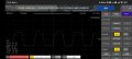
Output Voltage of UC3845 @ 60khz (measured using scoppy & rpi oscilloscope and arduino uno frequency meter , both build by me) , shows about 6.58 volts. I know these gadgets are any where near accuracy, But they should provide some help.

I think Gate threshold voltage is typical 3V. So @ 6.58 volt , it should switch , right ?

Attaching the the scoppy image for reference. One thing I am apprehensive is the Vmax shown on the scoppy . It is only 1.07V . Is it any relevant ?

Correct me where I am wrong.
 

Attachments

LowQCab

Joined Nov 6, 2012
5,101
The Acronym "SMPS" covers hundreds of various designs.

Please provide a complete list of your goals and specifications for this project.

"Most" designs will not have satisfactory performance without the aid of a good Oscilloscope.
"Some" of this dilemma can be overcome by over-specifying the various Component selections.

The combination of thinking that You are going to wind your own Transformer(s) or Choke(s),
and then having it operate efficiently at 50kHz is nothing but a "pipe-dream" for a beginner,
the chances of the end result being what You are expecting is slim to none.
Start-out below maybe ~10kHz, and use factory produced, and characterized, Transformer(s) and Choke(s).
.
.
.
 

Thread Starter

agsuresh

Joined Dec 28, 2023
66
UC3842 is good enough for a IRF840 @ 100kHz. Probably not at higher frequencies or with a bigger MOSFET.
It is OLD as @ronsimpson says, and so is the IRF840, but they both still work. You'll get performance like an OLD flyback design!
THere are lots of designs like that out there, still working and still being made.
Thank you,
I am trying to use it @50khz or 60khz. Most of ic with inbuilt mosfet work with these frequencies. The advantage is the transformer design depending on the frequency and topology (flyback....). So I can test use the same transformer with other ic's working on the same frequency.

I have seen many designs and modules working with these ics's. I have tried them. But I fail for some reason, unknown to me. Been trying for the past couple of weeks with various combination of circuit and transformer core and windings.

I have tried some other Ic's with in built mosfet. But they tend to get to damage easily even when checking the voltages using a digital voltmeter. I have burned several of them. UC384X looks far better. So far I have damaged only one mosfet (due to my mistake).

I can buy required modules from market that are cheap. But they tend to provide not even half of their claimed ratings. That is why I am trying to make one my own.
 

Thread Starter

agsuresh

Joined Dec 28, 2023
66
The Acronym "SMPS" covers hundreds of various designs.

Please provide a complete list of your goals and specifications for this project.

"Most" designs will not have satisfactory performance without the aid of a good Oscilloscope.
"Some" of this dilemma can be overcome by over-specifying the various Component selections.

The combination of thinking that You are going to wind your own Transformer(s) or Choke(s),
and then having it operate efficiently at 50kHz is nothing but a "pipe-dream" for a beginner,
the chances of the end result being what You are expecting is slim to none.
Start-out below maybe ~10kHz, and use factory produced, and characterized, Transformer(s) and Choke(s).
//Please provide a complete list of your goals and specifications for this project.//

Input AC between 176v to 264 volt (308 volt DC)
Output 13 DC 2Amp
Frequency 50khz
Topology : Flyback

// the chances of the end result being what You are expecting is slim to none.//
Yes, I am experiencing it. I posted here only after 3 weeks of trial. But can one give up ? That is easy.

I have tried some transformers used in other mps modules too. The result is not better. So I am sure if the problem is transformer entirely, but something else. I do understand I need a very good oscilloscope. However at this point I don't see investing in it financially viable , though I can afford it. (Rigol 200mhz 2 channel DSO is available at around $350 /- to $450/-)
 

LowQCab

Joined Nov 6, 2012
5,101
It sounds-like You are trying to make your project extremely small,
(something that You did not specify ).

Is there a reason that You are not simply using a Transformer--> Bridge-Rectifier-->Regulator ?????

Making projects really small just multiplies the complexity and headaches.
.
.
.
 

Ian0

Joined Aug 7, 2020
13,126
The Acronym "SMPS" covers hundreds of various designs.

Please provide a complete list of your goals and specifications for this project.

"Most" designs will not have satisfactory performance without the aid of a good Oscilloscope.
"Some" of this dilemma can be overcome by over-specifying the various Component selections.

The combination of thinking that You are going to wind your own Transformer(s) or Choke(s),
and then having it operate efficiently at 50kHz is nothing but a "pipe-dream" for a beginner,
the chances of the end result being what You are expecting is slim to none.
Start-out below maybe ~10kHz, and use factory produced, and characterized, Transformer(s) and Choke(s).
.
.
.
Off-the-shelf transformers simply are not available that work at 10kHz.
Start at 50kHz.
Buy a scope. You can probably get a usable scope for the cost of a few dozen dead MOSFETs
 

Ian0

Joined Aug 7, 2020
13,126
//Please provide a complete list of your goals and specifications for this project.//

Input AC between 176v to 264 volt (308 volt DC)
Output 13 DC 2Amp
Frequency 50khz
Topology : Flyback

// the chances of the end result being what You are expecting is slim to none.//
Yes, I am experiencing it. I posted here only after 3 weeks of trial. But can one give up ? That is easy.

I have tried some transformers used in other mps modules too. The result is not better. So I am sure if the problem is transformer entirely, but something else. I do understand I need a very good oscilloscope. However at this point I don't see investing in it financially viable , though I can afford it. (Rigol 200mhz 2 channel DSO is available at around $350 /- to $450/-)
Your circuit is almost correct. You need a higher voltage diode and a bigger capacitor on the DC output, and a lower resistance for R4 (try 330Ω).
Then it's all down to the winding of the transformer.
I suggest that you post the calculations for the transformer and a description of how you wound it.
@schmitt trigger is correct about the gap. You need to get it right.
It will work with a zener in the feedback circuit. You can move on to the TL431 later - TL431s are good but they can add their own stability problems!
 
Top