Facebook
 Google
 GitHub
 Linkedin
Dear all.
Hope you are fine, I didn't open the forum from a while...
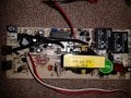
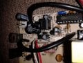
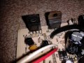
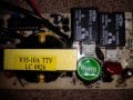
I'm trying to repair a 13.8V charger of a 600W inverter... The charger board is separate from the inverter board, as you see in the picture.
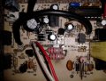
The charger has a 1000μF 25V capacitor at output, and it has a trimmer pot. to calibrate the output voltage between 13V and 14.5V (approximately). The problem now is that when I connect the AC input to the mains (220V), the charger should work fine and outputs 13.8V apprx., but it gives about 40V instead and the 25V output capacitor become hot of-course and tends to explode.. but I disconnect the mains plug instantly, and I find a 2C945P transistor became bad and I replace it...
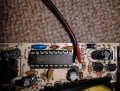
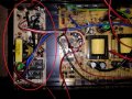
As you see the components on the board, I replaced the rectifier diodes at the AC input the first time I tried repairing, they were shorted, and I replaced the 2SC945 and a high voltage MOSFET at that time, I replaced it later too as it shorts when I try if the board is well repaired. The problem wasn't solved.
There is a microcontroller, I replaced it with a new one from another similar board, and replaced the transformer with a similar one too, and replaced the optocoupler and the triac\diac? with similar ones, but the same problem still exists. Ofcourse I tested the remaining parts (diodes, resistors, capacitors) and they are not many by the way... it's a small board.
I replaced the whole board with a new one and it worked fine, so there is some problem in that board.
In conclusion, I almost replaced the main parts with similar new ones, and tested the other parts and replaced some of them, but still didn't figure where is the remaining problem... Any recommendations or help is strongly appreciated.
Regards,
Hazim

Hope you are fine, I didn't open the forum from a while...
I'm trying to repair a 13.8V charger of a 600W inverter... The charger board is separate from the inverter board, as you see in the picture.
The charger has a 1000μF 25V capacitor at output, and it has a trimmer pot. to calibrate the output voltage between 13V and 14.5V (approximately). The problem now is that when I connect the AC input to the mains (220V), the charger should work fine and outputs 13.8V apprx., but it gives about 40V instead and the 25V output capacitor become hot of-course and tends to explode.. but I disconnect the mains plug instantly, and I find a 2C945P transistor became bad and I replace it...
As you see the components on the board, I replaced the rectifier diodes at the AC input the first time I tried repairing, they were shorted, and I replaced the 2SC945 and a high voltage MOSFET at that time, I replaced it later too as it shorts when I try if the board is well repaired. The problem wasn't solved.
There is a microcontroller, I replaced it with a new one from another similar board, and replaced the transformer with a similar one too, and replaced the optocoupler and the triac\diac? with similar ones, but the same problem still exists. Ofcourse I tested the remaining parts (diodes, resistors, capacitors) and they are not many by the way... it's a small board.
I replaced the whole board with a new one and it worked fine, so there is some problem in that board.
In conclusion, I almost replaced the main parts with similar new ones, and tested the other parts and replaced some of them, but still didn't figure where is the remaining problem... Any recommendations or help is strongly appreciated.
Regards,
Hazim
Attachments
-
 65.7 KB Views: 157