Slide Potentiometer

Thread Starter

RdAdr

Joined May 19, 2013
214
I have a slide
potentiometer and I used it on a voltage divider.
So I slide and the voltage changes from 0 to 5V, maybe.

Then I feed this voltage into the Arduino's ADC and I see that, even though the cursor is in some fixed position, the voltage varies a little. Thus the ADC outputs: 345, 346, 360, 344, 340, etc. So it does not output some fixed value like 345, but it kinda varies around this value.

So the voltage is not stable in the mV range. It is stable in the V range because if I measure with the multimeter I see 1.4V, for example, and not 1.4,1.5,1.3,1.4 etc. But always 1.4V.

My question. How do I stabilize the output voltage so that it stays fixed in the mV range too?

Obs: The supply voltage that feds the voltage divider comes from arduino and its very stable: 1023 always.
 
Last edited:

bertus

Joined Apr 5, 2008
22,920
Hello,

How stable is the input voltage to the voltage divider?
You can also try to add a capacitor on the output of the voltage divider.
You can also average some values in the Arduino.

Bertus
 

ericgibbs

Joined Jan 29, 2010
21,437
Obs: The supply voltage that feds the voltage divider comes from arduino and its very stable: 1023 always.
hi Rd,
The ADC measurement is ratiometric, so when measuring the MCU supply voltage it will always read 1023.
So its not a 'reliable' reference.

E
 

Thread Starter

RdAdr

Joined May 19, 2013
214
The input voltage to the voltage divider is the VCC of the Arduino and it is very stable. It stays always at 1023 if I read it on the ADC.

The two solutions seem good enough. I will see if I can make them work with the rest of my code. The output voltage of the divider is used as a variable reference for a closed loop control system.
 

Thread Starter

RdAdr

Joined May 19, 2013
214
hi Rd,
The ADC measurement is ratiometric, so when measuring the MCU supply voltage it will always read 1023.
So its not a 'reliable' reference.

E
I just used another reference coming from two 1.5 batteries in series and I see it is more stable. So the Arduino supply was the cause, not the potentiometer itself.

Although I still see some little varying. When the output voltage is minimum, i see : 104,107,105,103,108... which is better, but occasionally a value around 96 appears.

I think with a capacitor this will be solved even further maybe.
 

Alec_t

Joined Sep 17, 2013
15,117
The wires from the pot to the Arduino act as antennae and pick up interference, which can affect the measurement unless suppressed by use of a cap as suggested above.
 

ericgibbs

Joined Jan 29, 2010
21,437
hi Rd,
Connect a 1K resistor in series with the pot slider output and the ADC input, connect a 10nF cap from the ADC input to 0V
E
 

ericgibbs

Joined Jan 29, 2010
21,437
Isn't too small though? I was thinking more in the uF range.
The size of the capacitor will depend upon your application.
ie: if you want to measure slowly changing voltages then a higher cap value would be OK.
If you used a high value on rapidly changing input voltages, the readings could be incorrect.

What is your actual application.?
E

EDIT:
what is the resistive value of your potentiometer.?
 

Thread Starter

RdAdr

Joined May 19, 2013
214
The ADC measures once every 100 microseconds.

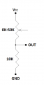
The potentiometer is in the image.

I guess 10nF seems ok.
 

Attachments

ericgibbs

Joined Jan 29, 2010
21,437
hi.
Your diagram looks wrong.?
Where does the pot slider go.?
E

BTW: a 50k pot is too high a resistance, the MCU's ADC input usually expect an input resistance of 10K or less
 

Thread Starter

RdAdr

Joined May 19, 2013
214
hi.
Your diagram looks wrong.?
Where does the pot slider go.?
E

BTW: a 50k pot is too high a resistance, the MCU's ADC input usually expect an input resistance of 10K or less
The pot slider is changed by my hand.

The OUT pin goes into the ADC. And the input resistance is below 10000 (if I remember thevenin's method correctly)
 

ericgibbs

Joined Jan 29, 2010
21,437
As you are changing the ADC input slowly by hand, a 100nF on the ADC input to 0v will be OK.
Are you always going to be changing the input by hand.?
 

Thread Starter

RdAdr

Joined May 19, 2013
214
Yes, only by hand. But I can't say that I will change it slowly or fast. My problem was that once changed to some position, the output voltage still varies due to noise or the supply voltage

And I think that when i change by hand and it goes suddenly from 1V to 3V, then the capacitor will have some delay, but if this delay is not really noticeable by eye, I wont care too much
 

bertus

Joined Apr 5, 2008
22,920
Hello,

According to your schematic, the voltage can vary between Vcc/6 and Vcc.
As said, the MCU will load the voltage divider quit a bit.
You could use a voltage follower between the voltage divider and the MCU input to aviod this.

Bertus
 
Top