Single Ended Wire on PCB

Thread Starter

DJ_AA

Joined Aug 6, 2021
490
Hi All,

I have a general question.

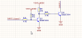
I have a PCB that has 3 wires connected to it: VCC, GND, and INPUT3. The INPUT3 connects to a GPIO pin. The wires are always connected, but sometimes we receive pulses on the input, which I believe is due to the wire behaving like an antenna, picking up some noise. However, since there is a pull-up resistor (R62), should this still be happening?


1726424497308.png
 

Attachments

panic mode

Joined Oct 10, 2011
4,864
if Q16 is off, then its collector circuit is high impedance and that could be a problem (sensitive to noise). if the device connected to it is also high impedance (or has weak pull up resistor), then this is more than likely. you can add low value pullup (such as 1k) and see if the problem goes away.
 

MisterBill2

Joined Jan 23, 2018
27,164
With the circuit fragment shown in post #1, and the description telling us that a pulse appears on a fragment of that circuit, it is not possible to provide a USEFUL guess as to the problem, other than to let you know that it originates in an area that we are not shown. That much is totally clear to me.
 

Thread Starter

DJ_AA

Joined Aug 6, 2021
490
Thanks @ronsimpson

I am also thinking about removing the transistor and simply connecting the signal to GPIO, i can do the level conversion in my code.

Ideally in the both pull up and pulldown. Pull up if the sensor is open collector, and pull down is sensor is disconnected but i have extension wire connected to my PCB.
1727202600693.png
 

MisterBill2

Joined Jan 23, 2018
27,164
I did not suggest changing the voltage. I commented that possibly that is what another saw as indicating that it looked like an output.
As for a pulse appearing at the input, is it a pulse that should be appearing, or one that should not appear?? Is that wire routed near some noise source? Should that wire be shielded to prevent noise pickup??
 

Thread Starter

DJ_AA

Joined Aug 6, 2021
490
@MisterBill2

I will be not be able to change the voltage, therefore i have redesigne the circuit below. If i am correct with this design, my Sensor Puslse can be any Voltage, Open Collector and GND, and the pulse on my GPIO would either be 3.3V or GND. Is this a correct design?

1732989722871.png
 
Top