Sine wave oscillator with TL071 : How to modify the amplitude level ?

LowQCab

Joined Nov 6, 2012
5,101
A true, accurate, Sine-Wave-Oscillator is not a simple project.

First we need to know the intended end-usage of the Oscillator.

Does it need to create a very low-distortion, accurate Sine-Wave, or
simply a Waveform that's pretty close to a Sine-Wave ?

What Impedance must it be capable of driving ?

What type of Circuit will it be driving ?

What does the Peak-to-Peak Output-Voltage need to be ?,

Will the Frequency need to be adjustable, or fixed ?,
if adjustable Frequency, what is the Frequency-Range needed ?,
if fixed Frequency, what is the Frequency desired ?

Does the Frequency need to be accurate, and stable ?

What was the original purpose of building this Oscillator ?
.
.
.
 

sparky 1

Joined Nov 3, 2018
1,218
Getting the sine wave centered close to Zero.
You can think about that control adjustment as part of a split supply. Some designs have very finite adjustment.
This usually involves positive and negative voltage regulators. There are premade modules available.
I think by the time you get a single supply to be filtered, stable and get very close to zero that split supply may be a better option.
 
Last edited:

Thread Starter

Philexium

Joined Oct 15, 2017
110
A true, accurate, Sine-Wave-Oscillator is not a simple project.

First we need to know the intended end-usage of the Oscillator.

Does it need to create a very low-distortion, accurate Sine-Wave, or
simply a Waveform that's pretty close to a Sine-Wave ?

What Impedance must it be capable of driving ?

What type of Circuit will it be driving ?

What does the Peak-to-Peak Output-Voltage need to be ?,
Will the Frequency need to be adjustable, or fixed ?,
if adjustable Frequency, what is the Frequency-Range needed ?,
if fixed Frequency, what is the Frequency desired ?
Does the Frequency need to be accurate, and stable ?
What was the original purpose of building this Oscillator ?

.
.
Good morning @LowQCab

Here are the answers :

1-Intended end-usage of the Oscillator :
- It is designed to make quench oscilltor for a superregenerative receiver I have already built

2 - Does it need to create a very low-distortion, accurate Sine-Wave, or
simply a Waveform that's pretty close to a Sine-Wave ?
- As close as possible but not a low distorsion

3- What Impedance must it be capable of driving ? : I need to calculate it

4-What type of Circuit will it be driving ?
- See answer 1

5-What does the Peak-to-Peak Output-Voltage need to be ?
- Min. 0 to 3 Volts but I would like to test 0 - close to 9 V

6-Will the Frequency need to be adjustable, or fixed ?,
if adjustable Frequency, what is the Frequency-Range needed ?,
if fixed Frequency, what is the Frequency desired ?
- Ideally from 30 kHz to about 150 kHz

7-Does the Frequency need to be accurate, and stable ?
- Not critical

8-What was the original purpose of building this Oscillator ?
- See answer 1

Again, thak you for your time and help !
Philippe
 

ericgibbs

Joined Jan 29, 2010
21,541
hi Phil.
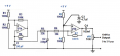
Look at this Option uses a R2R OPA.
E


Added AD820 datasheet.
https://www.analog.com/en/products/ad820.html#product-discussions
Clip:

It has true single-supply capability, with an input voltage range extending below the negative rail, allowing the AD820 to accommodate input signals below ground in the single-supply mode. Output voltage swing extends to within 10 mV of each rail, providing the maximum output dynamic range.

EG 1141.png
 

Attachments

Last edited:

Thread Starter

Philexium

Joined Oct 15, 2017
110
I would like to clarify again one point :

I need the "bottom" of the sine wave to be at 0V, NOT centered at 0 V
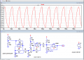
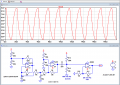
See the "simulation" photo attachedSine wave simulation.jpg
Thank you !
 

Thread Starter

Philexium

Joined Oct 15, 2017
110
hi,
Post #27 shows just that!
E
Good morning Eric !

Yes it's great !!!
I am sorry but the messages were crossed each other :)

I have to order some AD820 : a little bit expensive but those AD chips are very powerful !

I am eager to test it !
Thank you again for your time and LTSpice simulation.

Philippe
 

sparky 1

Joined Nov 3, 2018
1,218
OK SRR, NOT a supply issue and not a sine wave but an amplitude modulated signal. Approaching the threshold of thermal noise in a super regen used in an SRR receiver. An introduction Chapter 1.2 defines SRR and a successful electrical model shown in chapter 5 makes it possible to study the effects.
https://mobt3ath.com/uplode/books/book-77667.pdf

Describing thresholds in positive feedback and use of a square wave the article below says Despite the noise( in this case a screech ), A clean square wave is produced. (It is also the rate of sampling which is used for reshaping.) Shown in the next to last illustration and explained in the paragraph.
https://www.allaboutcircuits.com/textbook/semiconductors/chpt-8/positive-feedback/
 
Last edited:

AnalogKid

Joined Aug 1, 2013
12,242
OK, let's see if I have this correct.

You want to be able to vary the peak-to-peak amplitude of the generated sine wave (turn it up and down) , while keeping the negative peaks of the waveform at 0 V.

Yes / No - ?

If yes, that is not a simple thing to do. One approach would be a comparator/peak detector and/or integrator driving a DC-offset servo.

And - why? Why is it important that the negative peaks of the waveform sit at 0 V no matter what the amplitude?

ak
 
Top