Simulating laser diode driver circuit and ldr reciever circuit using proteus or any other simulation software

Thread Starter

vasanth2304

Joined Mar 5, 2024
4
ckt2.png 
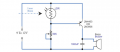
this is a security system when the laser beam is interrupted, ldr should detect and buzzer should ring. The second image is a laser diode driver circuit and the first one is ldr circuit. I tried simulating this in various softwares can someone help me simulating this
 

Attachments

eetech00

Joined Jun 8, 2013
4,061
Can you help me in finishing this simulation
1. The PNP transistor is your project file is reversed.

2. For simulation purposes, If you want to control the LDR using input from the laser diode (LD), you'll need to couple the LD current with the LDR current based on a current transfer ratio that you determine.
 

ericgibbs

Joined Jan 29, 2010
19,194
Hi eetech.
How is the PNP reversed?

If I understand correctly, the TS wants the buzzer to operate when the laser beam is broken, as shown in the simulation.?

E
 

eetech00

Joined Jun 8, 2013
4,061
Hi eetech.
How is the PNP reversed?
I opened the TS Proteus project file and the PNP transistor is not connected as you correctly show on your schematic.
The emitter/collector are reversed.

If I understand correctly, the TS wants the buzzer to operate when the laser beam is broken, as shown in the simulation.?

E
Yes. And that will depend on the laser diode intensity, which is affected by the current flow thru it.
The LD light intensity, focused on the LDR, determines the LDR resistance, which, in turn, determines when the transistor turns on/off the buzzer.

If all the TS wants is an on/off alarm simulation, just use a switch. :D
 

itskrish

Joined Mar 2, 2024
11
I opened the TS Proteus project file and the PNP transistor is not connected as you correctly show on your schematic.
The emitter/collector are reversed.


Yes. And that will depend on the laser diode intensity, which is affected by the current flow thru it.
The LD light intensity, focused on the LDR, determines the LDR resistance, which, in turn, determines when the transistor turns on/off the buzzer.

If all the TS wants is an on/off alarm simulation, just use a switch. :D
Bro can you give me a simulation filee
I opened the TS Proteus project file and the PNP transistor is not connected as you correctly show on your schematic.
The emitter/collector are reversed.


Yes. And that will depend on the laser diode intensity, which is affected by the current flow thru it.
The LD light intensity, focused on the LDR, determines the LDR resistance, which, in turn, determines when the transistor turns on/off the buzzer.

If all the TS wants is an on/off alarm simulation, just use a switch. :D
Can anyone attach the simulation file
To run the crct ckt
 

ericgibbs

Joined Jan 29, 2010
19,194
hi its,
It is AAC policy not to give final or complete answers to Homework assignments.
Only hints and/or guidance.

Moderation.
 
Top