Simplest way to control 180vDC motor with PWM

Thread Starter

BigAlscorpio

Joined Feb 5, 2015
52
Yes, actual circuits or just pictures may help us figure out what is going on.
Another thing you could try is to run the motor in series with a 240V 100W lamp for a start. It probably will not drive much mechanical load but it will see if the motor works.
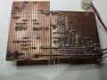
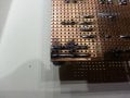
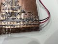
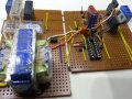
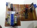
I thought the pics from my phone would be better than this. oh well. The missing IC was the PIC, a 16f628a I believe and the 8 pin is a max627 dual power fet driver. I will try and draw out the circuit but sadly this was my last attempt and the most convoluted one, doh! It would be the only one I can find eh! The relay is meant to hold off the power to the fet until the PIC has initialized fully. The rest I just can't remember, had a family member ill for a time and had to shelve it but it may come back as I try to trace it out. Here are the pics.

20180407_185444.jpg 20180407_185450.jpg 20180407_185450.jpg 20180407_185457.jpg 20180407_185522.jpg 20180407_185522.jpg 20180407_185528.jpg
 

Thread Starter

BigAlscorpio

Joined Feb 5, 2015
52
A few clues, the blue 2 pin block is the AC in and the 3 pin one is for the FET. After going through a few I made them easier to change. The motor out is a red and black pair soldered beneath it. The opto is to keep the PIC safe from the relay both back emf and mains AC.The tall TO220 is a 7812 for the driver power and the other shorter one is an ultrafast diode for the FET. I will try and draw asap, it's times like this when I wish I were BigClive, he makes reverse engineering look so easy!
Edit, oh and yes the left hand bottom corner of the first pic IS the result of an explosion some time in the past, could have been the last thing that happened or I may have had tries after that, just can't remember.
Al
 
Last edited:
Top