simplest bridge amplifier with transistors

Audioguru again

Joined Oct 21, 2019
6,673
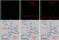
My simulations show that bootstrapping makes a much better audio amplifier:
1) AC gain is increased.
2) Distortion is much less.
3) Max undistorted output power is much more.

The inductance of a speaker causes the impedance to be higher at high audio frequencies causing less loading of the amplifier.

The speaker inductance causes a phase shift that might cause an amplifier to oscillate at a high frequency if the circuit has no frequency compensation capacitor (that all opamps have). The high frequency oscillation might cause heating in the output transistors even without an input signal.
 

Attachments

Thread Starter

mike_canada

Joined Feb 21, 2020
239
I don't know if I can get any more perfect than this. I find that playing with R5 changes the height of the green waveform but the green waveform does not look as natural as the blue one. Could it be because of my emulated speaker?

And I think I am OK with transistors this time, but I'll definitely need to invest in some 1W resistors (and I say invest because prices skyrocket while many people's income is low)

wf.png
 

Audioguru again

Joined Oct 21, 2019
6,673
The TDA7266 amplifier IC costs $10.66 plus shipping at Digikey in Canada. It has 2 bridged amplifiers in it.
They have a wide range of distortion, some are hifi with low distortion and others have high distortion above only 2W.

The discrete parts amplifier in post #42 has its R5 connected to the wrong place. I showed the correct wiring in post #22.
Reduce the resistance of R5 to increase the level of output b.
It looks like the resistances of R3 and R12 are too high causing clipping at the top of output a.
 

Attachments

Thread Starter

mike_canada

Joined Feb 21, 2020
239
The discrete parts amplifier in post #42 has its R5 connected to the wrong place.
I'll try the other place again as you mentioned.

It looks like the resistances of R3 and R12 are too high causing clipping at the top of output a.
Might also be my input amplitude since I played with that the most. but I'll look at those resistors again. I think they also control gain, but then again, what math should I apply to such resistors? R3 = pull-up resistor to VCC times transistor Hfe?
 

Audioguru again

Joined Oct 21, 2019
6,673
Any transistor's hFE can be fairly low or fairly high. The hFE of two of them probably do not match.
Resistors inside an IC usually march fairly well.

Resistors R3 and R12 provide AC and DC negative feedback. AC feedback affects AC amplification and DC biasing affects symmetrical clipping.

R3 and R12 do not pull-up to VCC. Instead they are fed from the output of its associated amplifier for negative feedback.
 

Thread Starter

mike_canada

Joined Feb 21, 2020
239
I must have confused you. I'll retry my math.

(Transistor Hfe) x (pull-up resistor R4) = (ideal resistor R12)
(Transistor Hfe) x (pull-up resistor R8) = (ideal resistor R3)

I think that's sortof the math to calculate the best R12 and R3 values?
 

Audioguru again

Joined Oct 21, 2019
6,673
You do not know the hFE of each transistor. It might be high, medium or low.
The hFE affects a transistor's DC current gain, not voltage gain. The amount of current in a resistor affects its voltage.
R4 and R8 are part of the collector loads on Q7 and Q8 and have only a small affect on their DC base biasing.
 
Top