Simple Timer Circuit - Will this circuit work?

Audioguru again

Joined Oct 21, 2019
6,691
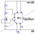
RB in the circuit on the datasheet for the n555 IC is the variable resistor. Look in Google to see how to connect it on the 555 circuit. Ohm's Law and datasheets of the parts are used to calculate resistor values.
 

sghioto

Joined Dec 31, 2017
5,390
I'm following Sghito's Wiring diagram. It does not use pin 7.
The schematic I posted is correct, pin 7 is not used in this particular application. From the video I believe I see the problem.
The orange and green wire from the pot should connect to the combo of pin2 and pin6 and the minus lead of the cap. It appears it's connected to the supply line from the switch which would explain why it got fried previously.
 

Audioguru again

Joined Oct 21, 2019
6,691
The schematic I posted is correct, pin 7 is not used in this particular application.
No Sghioto, your schematic is wrong because nothing discharges the capacitor, and you show both the capacitor and the pot connected to wrong places. Also a resistor is missing that prevents the pot from burning.

A 555 oscillator uses a resistor in series with either pin 7 or pin 3 to discharge the capacitor. That is why pin 7 is called the discharge pin. Here is how it should be connected:
 

Attachments

sghioto

Joined Dec 31, 2017
5,390
No Sghioto, your schematic is wrong
Sorry but I have to correct you. The circuit is a variation of a monostable not astable as you show. It's a classic circuit used for generating a negative or positive pulse determined by the location of the timing capacitor when power is first applied.
When power is removed the cap discharges through the pot and the 555 itself. Usually a reversed biased diode is place across the pot to quickly discharge the cap.
EDIT:
Also a resistor is missing that prevents the pot from burning.
I do agree a resistor should be added to the pot as C1 is a large value and depending on the setting of the pot it could be damaged.
Adding R2 a 1K resistor will avoid any damage and give a minimum delay of 1.1 seconds
1630596363332.png
 
Last edited:

Audioguru again

Joined Oct 21, 2019
6,691
The original circuit has a power supply pushbutton. You push the button and nothing happens unless you hold the button pushed during the entire timing period. A useless circuit.
 

Thread Starter

David Nolan

Joined Aug 4, 2021
30
I got it working, using sghioto's original circuit. I want to thank everyone for their contribution and helping me out, I appreciate it. Special thanks to sghioto for drawing out a a circuit diagram and pointing out my mistakes. I imagine if I connect this to a solenoid relay I'm going to need use the second circuit provided in post #44
 

Thread Starter

David Nolan

Joined Aug 4, 2021
30
Your welcome, glad you got it working.

Most likely the 555 will not be able to drive a solenoid direct, you will need a driver circuit.
Usually consisting of some type of transistor depending on the solenoid chosen.

I noticed in the original video I linked, the led was simply replaced with a solenoid relay. I'm sure as everyone has said that video might be fake but I was just wondering if it's capable of sending a 9V signal, why wouldn't it be able to open and close a solenoid switch? Is it a case of the back EMF frying the 555 timer circuit and is there not a convenient way around that with a few extra components?

Personally, I just need this circuit to drive a 3V vibrating disc motor in place of the LED, should be fine as long as I add a resistor so the disc motor isn't fried or is there a fault in that logic?
 

Thread Starter

David Nolan

Joined Aug 4, 2021
30
Can you provide a link to this motor?
It depends on how much current the motor draws.

Here's the one's I have... If you run them on anything over 3 Volts, the connecting wires die as they are a very small diameter. It states 80mA

Link: https://www.amazon.co.uk/gp/product/B07T7GF62Z/ref=ppx_yo_dt_b_asin_title_o02_s00?ie=UTF8&psc=1

I got the motor to work with a 1K resistor on a separate board, using 30 Volts, which obviously isn't a good idea in the long term 'haha'
I'm guessing I need a lower ohm resistor?
 
Last edited:
Top