Simple Relay

Thread Starter

Justinj8k2

Joined Nov 13, 2014
8
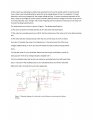
In this project you will design a simple relay-activated circuit used to quickly switch an electrical load from a solar array to backup batteries when the array voltage drops too low. For example, if a cloud obscures a solar array temporarily, the output voltage will sag. To ensure continuous operation of the load, a relay circuit might be used to switch to battery backup until the voltage of the solar array returns to normal. Basically, your “design” will consist of figuring out the inductance necessary on the relay coil to meet the design specifications

The relay/circuit you will use is shown in Figure 1. The design specifications:

1) The solar cell system normally operates at 24 V DC when fully illuminated.

2) The relay has a winding resistance of 60 Ω. But the inductance of the relay coil is to be determined by you.

3) The relay switches instantaneously when the coil current drops to 0.3 A or below.

Your job: 1) Calculate the value of coil inductance, L, that will ensure that if the array

voltage suddenly drops to 16 V, the relay will switch the load to battery backup within

0.25 s.

2) Using the value of L you calculated, determine how long it would take to switch to

backup power if the array voltage abruptly changed to 0 V.

3) Find a standard relay that has the coil resistance and inductance that will meet these

specs. If you can’t find anything close to your calculated value, then find a relay with

different R and L that will still work in this application.


Having a little trouble. Where should I start?
 

Attachments

WBahn

Joined Mar 31, 2012
30,088
The first thing is to show YOUR attempt to work YOUR homework problem.

The first step in that is to examine the requirements and describe what you think is going on and what it being asked of you. You can't solve a problem until you understand what the problem is.
 

Thread Starter

Justinj8k2

Joined Nov 13, 2014
8
The first thing is to show YOUR attempt to work YOUR homework problem.

The first step in that is to examine the requirements and describe what you think is going on and what it being asked of you. You can't solve a problem until you understand what the problem is.
I'm assuming that this is a simple first order circuit problem. I believe it can represented with a resistor and a inductor. I think the way to proceed is to calculate time constant. Am I on the right path? I have not started any calculations yet. This is a group project with many parts. This was the only part that I was unsure of. I have yet to meet with the group. Just gathering information. I'm not looking for ready made solution. Just Idea of whats to do. Im not sure what the YOUR's are about.
 
Last edited:

WBahn

Joined Mar 31, 2012
30,088
Yes, you are on the right path with regard to it being related to the time constant. Can you figure out the relationship between the time constant and the time it takes for the relay to drop out under the conditions specified?
 

Thread Starter

Justinj8k2

Joined Nov 13, 2014
8
Yes, you are on the right path with regard to it being related to the time constant. Can you figure out the relationship between the time constant and the time it takes for the relay to drop out under the conditions specified?
Thanks for your comments! I have got it figured out, for the most part.
 

WBahn

Joined Mar 31, 2012
30,088
My first thought was that an inductance of 10 H on a coil relay is awfully high, so I sanity checked it by seeing what value of inductance would give a 250 ms time constant when in series with a 60 Ω resistor and that came out to be 15 H. So an answer in that general range is probably what you are looking for. If I were doing this problem, this kind of quick and dirty estimate is one of the first things I would do so that once I have an answer I can see if it makes any sense at all. In this case your answer passes this test.

When I worked it I got L = 10.82 H, which is within about 5% of what you got. Quickly looking at your work my guess is that you are letting roundoff errors get to you. It's of course always possible that I made a mistake, too.

I would STRONGLY advise you to get in the habit of always, always, ALWAYS tracking your units throughout your work. Most mistakes you will make will mess up the units, if they are there, and let you find them at the point where you make them or at least be able to track them down later much more quickly. Do NOT just tack whatever units you WANT the answer to have onto the end.

Your solution approach is just fine, but you don't need to resort to differential equations on basic circuits most of the time. This is a first order circuit and so you know the response will be first order of the form:

\(
i(t) \. = \. I_f + (I_i - I_f)e^{-\frac{t}{\tau}}
\)

You are looking for the value of t=T at which this is equal to the threshold current, I_th. Actually, of course, you are looking for the time constant because you are given T.

\(
I_{th} \. = \. I_f + (I_i - I_f)e^{-\frac{T}{\tau}}
\)

So solve for the time constant:

\(
\tau \. = \. \frac{T}{\ln \( \frac{I_{th}-I_f}{I_i-I_f} \)} \. = \. \frac{L}{R}
\)

\(
L \. = \. \frac{RT}{\ln \( \frac{I_i-I_f}{I_{th}-I_f} \)}
\)

Now you have a solution in general form that you can use and also that you can quickly manipulate to answer the next question. Let's play around with this a bit before we use it further. We know that our question is asking about switching times due to changes in solar cell output voltage. So let's run with that.

\(
L \. = \. \frac{RT}{\ln \( \frac{\frac{V_i}{R}-\frac{V_f}{R}}{I_{th}-\frac{V_f}{R}} \)}
\)

Multiply through by the resistance (in the ln() call):

\(
L \. = \. \frac{RT}{\ln \( \frac{V_i -V_f }{ I_{th}R-V_f } \)}
\)

You now have something that is in a very friendly form. For the inductance:

\(
L \. = \. \frac{(60\Omega)(0.25s)}{\ln \( \frac{24V -16V }{ (0.3A)(60\Omega)-16V } \)} \. = \. \frac{15H}{ln \( \frac{8V}{2V}\) } \. = \. \frac{15H}{ln(4)} = 10.82 H
\)

Notice how I worked symbolically right up to the end. This let's me do a number of useful things. First, if parameters change (we now are working with a coil that has 100 Ω of resistance and drops out at 75 mA), then it is trivial to recalculate the results. Second, it let's me easily identify which parameters affect what in the results. Third, it let's me minimize the amount of roundoff error that I introduce. Finally, it let's me manipulate things to answer slightly different questions very easily, such as how long it will take to drop out if the solar cell voltage suddenly drops to zero, hint, hint.
 

Thread Starter

Justinj8k2

Joined Nov 13, 2014
8
My first thought was that an inductance of 10 H on a coil relay is awfully high, so I sanity checked it by seeing what value of inductance would give a 250 ms time constant when in series with a 60 Ω resistor and that came out to be 15 H. So an answer in that general range is probably what you are looking for. If I were doing this problem, this kind of quick and dirty estimate is one of the first things I would do so that once I have an answer I can see if it makes any sense at all. In this case your answer passes this test.

When I worked it I got L = 10.82 H, which is within about 5% of what you got. Quickly looking at your work my guess is that you are letting roundoff errors get to you. It's of course always possible that I made a mistake, too.

I would STRONGLY advise you to get in the habit of always, always, ALWAYS tracking your units throughout your work. Most mistakes you will make will mess up the units, if they are there, and let you find them at the point where you make them or at least be able to track them down later much more quickly. Do NOT just tack whatever units you WANT the answer to have onto the end.

Your solution approach is just fine, but you don't need to resort to differential equations on basic circuits most of the time. This is a first order circuit and so you know the response will be first order of the form:

\(
i(t) \. = \. I_f + (I_i - I_f)e^{-\frac{t}{\tau}}
\)

You are looking for the value of t=T at which this is equal to the threshold current, I_th. Actually, of course, you are looking for the time constant because you are given T.

\(
I_{th} \. = \. I_f + (I_i - I_f)e^{-\frac{T}{\tau}}
\)

So solve for the time constant:

\(
\tau \. = \. \frac{T}{\ln \( \frac{I_{th}-I_f}{I_i-I_f} \)} \. = \. \frac{L}{R}
\)

\(
L \. = \. \frac{RT}{\ln \( \frac{I_i-I_f}{I_{th}-I_f} \)}
\)

Now you have a solution in general form that you can use and also that you can quickly manipulate to answer the next question. Let's play around with this a bit before we use it further. We know that our question is asking about switching times due to changes in solar cell output voltage. So let's run with that.

\(
L \. = \. \frac{RT}{\ln \( \frac{\frac{V_i}{R}-\frac{V_f}{R}}{I_{th}-\frac{V_f}{R}} \)}
\)

Multiply through by the resistance (in the ln() call):

\(
L \. = \. \frac{RT}{\ln \( \frac{V_i -V_f }{ I_{th}R-V_f } \)}
\)

You now have something that is in a very friendly form. For the inductance:

\(
L \. = \. \frac{(60\Omega)(0.25s)}{\ln \( \frac{24V -16V }{ (0.3A)(60\Omega)-16V } \)} \. = \. \frac{15H}{ln \( \frac{8V}{2V}\) } \. = \. \frac{15H}{ln(4)} = 10.82 H
\)

Notice how I worked symbolically right up to the end. This let's me do a number of useful things. First, if parameters change (we now are working with a coil that has 100 Ω of resistance and drops out at 75 mA), then it is trivial to recalculate the results. Second, it let's me easily identify which parameters affect what in the results. Third, it let's me minimize the amount of roundoff error that I introduce. Finally, it let's me manipulate things to answer slightly different questions very easily, such as how long it will take to drop out if the solar cell voltage suddenly drops to zero, hint, hint.
Thanks again for your input. You've given me some great advice. Your approach is better. I did round some numbers off for simplicity, probably where the difference happened. I truly appreciate all the time and effort.
 

Thread Starter

Justinj8k2

Joined Nov 13, 2014
8
Thanks again for your input. You've given me some great advice. Your approach is better. I did round some numbers off for simplicity, probably where the difference happened. I truly appreciate all the time and effort.
I am having trouble finding a standard relay that would meet these conditions. Do you have any suggestions on where and how to look?
 

WBahn

Joined Mar 31, 2012
30,088
Assuming you can find a coil with 60 Ω, if you found one that had an inductance of 500 mH and one that had an inductance of 20 H, would either of these meet the requirements stated in the problem?

If you can't find a 60 Ω coil but can find a 150 Ω coil and a 20 Ω coil, which would be the better choice (assuming a suitable inductance can be found)?

If you could only find coils with 100 Ω resistance, would 10.82 H still be the nominal inductance?
 

Thread Starter

Justinj8k2

Joined Nov 13, 2014
8
Assuming you can find a coil with 60 Ω, if you found one that had an inductance of 500 mH and one that had an inductance of 20 H, would either of these meet the requirements stated in the problem?

If you can't find a 60 Ω coil but can find a 150 Ω coil and a 20 Ω coil, which would be the better choice (assuming a suitable inductance can be found)?

If you could only find coils with 100 Ω resistance, would 10.82 H still be the nominal inductance?
I cant really find anything related to the inductance. I was mostly looking under the other requirements. I was hoping that I could find one using the resistance amperage and voltage. From what I gather, relays are measured based on few values. Contact Voltage, coil resistance, coil voltage, contact amps are a few that I was looking at. It varies from source to source. Since the it is suppose to switch at .3 A, I figured that the coil voltage should be at 18V. I just assumed that contact voltage/amperage is some sort of max input. The problem is that anything around 60 Ohms only has a coil voltage around 12v dc. So... I think that I may not understanding these values correctly or my requirements are too limiting.
 
Top