Simple P-channel mosfet switch doesn't function

Thread Starter

Elazar

Joined Oct 29, 2019
49
The below p-channel MOSFET circuit is configured to work as a simple high side power switch,

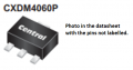
The circuit works fine with the IRF9Z34STRLPBF MOSFET Datasheet but it doesn't work with the CXDM4060P Datasheet
They are both P-channel MOSFETs (ENHANCEMENT-MODE)

I use both chips for two different circuits with different current requirements.

CXDM4060P chip test:
Vgs -12v
drain GND = 0v
VCC drain = 11.6V
------------------
Vgs 0v
drain GND = 0v

IRF9Z34STRLPBF chip test:
Vgs -12v
drain GND = 24v
-----------------
Vgs 0v
drain GND = 0v
1637683475566.png
 

crutschow

Joined Mar 14, 2008
34,282
Is this just a simulation?
If it doesn't work in a real circuit, then the MOSFET is faulty or you have it connected wrong (double check its pinout).
 

Thread Starter

Elazar

Joined Oct 29, 2019
49
I have double-checked, and the footprint pinout is correct,

However, in the datasheet the mechanical outline and the pin configuration (top view) are opposite? something doesn't make sense?

1637687573254.png
 

djsfantasi

Joined Apr 11, 2010
9,156
I have double-checked, and the footprint pinout is correct,

However, in the datasheet the mechanical outline and the pin configuration (top view) are opposite? something doesn't make sense?

View attachment 253325
Triple check. I see the pin configuration as being the same in both views. In the back view, the tab is facing you. Rotating that view to the top, without changing anything else, pin 1 is to the left. But the tab is in the front. Rotating that view 180 degrees so the tab is to the back (as it is in the datasheet top view), brings pin 1 to the right. The same as in the datasheet.
 

Thread Starter

Elazar

Joined Oct 29, 2019
49
I have checked one more time, and I dont see any problem with the pinout or circuit, BUT it dosnt work correctly

See picture of the footprint on the PCB...

1637690037899.png
 

crutschow

Joined Mar 14, 2008
34,282
BUT the mechanical outline picture shows that it is correct??
Not correct.
That view is the bottom of the MOSFET so you need to look from the bottom of the board through to the top, to see how it connects.

Do you not see that both view of the MOSFET are correct?
 
Last edited:

Thread Starter

Elazar

Joined Oct 29, 2019
49
Not correct.
That view is the bottom of the MOSFET so you need to look from the bottom of the board through to the top, to see how it connects.

Do you not see that both view of the MOSFET are correct?
It's a simple SOT-89 standard case? and I took the footprint from the Kicad library, without changing it...
The footprint is correct, is the datasheet top view wrong?
 

AnalogKid

Joined Aug 1, 2013
10,986
The footprint is correct, is the datasheet top view wrong?
No, it isn't. Pay attention.

The image in post #3 has two *different* views of the *same* package. The upper drawing is the part viewed from its bottom, or back, or solder side. That is why you can see the outline of the thermal pad area.

The lower drawing (labeled "Top View") is the same package viewed from the top or front side. The pin numbers are reversed between the two views because the part is flipped over.

ak
 

crutschow

Joined Mar 14, 2008
34,282
The footprint is correct, is the datasheet top view wrong?
No
What do you mean, "the footprint is correct"?
The footprint can be physically correct but the pinout not correct.
As we've said several times, both datasheet views are correct.
One is from the top and one is from the bottom.
Don't you understand that reverses the apparent sequence of the pins?
Are you dyslexic?
 

BobTPH

Joined Jun 5, 2013
8,812
The numbering of the pins in the top view is odd, right to left instead of the usual left to right. Is it an Israeli made device?

Bob
 

Thread Starter

Elazar

Joined Oct 29, 2019
49
Okay,

Just to make the question clear:

The chip is a standard SOT-89 package, and usually, the pinout (pin 1) is part of the standard,

As you can see in this document: Link

The picture below is in top view (hopefully) and it is a standert SOT-89 package... thats why I am confused...
1637737602215.png
 

BobTPH

Joined Jun 5, 2013
8,812
Okay,

Just to make the question clear:

The chip is a standard SOT-89 package, and usually, the pinout (pin 1) is part of the standard,

As you can see in this document: Link

The picture below is in top view (hopefully) and it is a standert SOT-89 package... thats why I am confused...
View attachment 253362
I told you that in my last post. They have numbered the pins in a non-standard way.

Edit: You have to go by the datasheet.

Bob
 
Last edited:
Top