Simple LED circuit help pls

Thread Starter

sztriki

Joined Feb 10, 2019
12
Hi all,
Total noob here, so please go easy on me :)
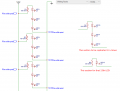
I'm doing a simple UV LED strip for a project (would be blacklight for a UV patinting). I'm really a dummy when it comes to theory but so far have been able to limp along with a circuit planner. I did the same now using this circuit plan:


It's 25 UV LEDs running from a 9V battery with a 330 Ohm resistor at every LED's negative leg. LEDs are 3-3.V forward voltage, 20mA forward current.

So I wired up like this, all long legs soldered together, all short ones with respective resistors soldered together, the only difference is that I soldered the battery socket to the last LED instead of in the middle as in the image.
The result however was this.

The LED to which the battery socket is soldered to is off completely, the one after is bright, the one after is faded and it simply just fades out after 3-4 LEDs. I tried putting the battery socket somewher else in the circuit but was the same, one it's wired to is dead, the one after is bright then fades out.
I always thought the resistors should go on the long (positive) legs, but the circuit diagram showed otherwise so I went with this. Tried other batteries too, but granted they weren't the freshest but AFAIK it should be uniformly faded if the battery is low. Any tips or idea what it could be?
Much appreciated!
 

Marc Sugrue

Joined Jan 19, 2018
222
Sounds like you are overloading/discharged the 9V battery to me. The Brightest LED is probably because it has the Lowest Vf so it is still allowing some current to flow. Measure your volts and verify its still 9V as the battery discharges the voltage will drop.

Further to this you may find this website useful http://www.learningaboutelectronics.com/Articles/Battery-internal-resistance

a 9v battery can have a source impedance of about 2Ohms meaning at the 500mA your pulling you volts will not be 9V but 8V.

V = I x R = 0.5 * 2R = 1V

So i would say you either need a better source of voltage OR a lighter load i.e increase your series resistor.

Hope this helps
 
Last edited:

crutschow

Joined Mar 14, 2008
34,281
The LED to which the battery socket is soldered to is off completely, the one after is bright
Sounds like something is not wired correctly.

Measure the battery voltage when it is connected to the LEDs.
I expect it is much less than 9V, especially if it is not fresh.

And even a fresh 9V battery will not supply 500mA for very long. :eek:
You need some AA, C, or D alkaline cells in series to provide that much current.
AA's will only last a few hours at that current level.
D's would probably last more than a day.
Better to use a wall-wort, if you can.

Since your eye is not sensitive to UV (hence the name), they may be running brighter than you think.
 

Bernard

Joined Aug 7, 2008
5,784
What kind of wire are you using to connect LEDs & resistors ?
That 9V battery is a poor choice. 3 AA alk. would be slightly better with new Rs.
 

iONic

Joined Nov 16, 2007
1,662
My question for you is...how old is that 9V battery? From what I am reading, the max current draw is probably not more that 500mA, which is the draw of your circuit as drawn up(see bottom line spec). The batteries capacity is about 500maH-550MaH. This means that the circuit may be able to run for an hour before it begins to crap out on you. Try a fresh battery and see what happens. If this fails you can try a series/parallel configuration as seen below. You will notice that the current draw of this circuit is only 260mA, about half of the previous one. This equates to a max of 2hrs run time...still not good if you intend to leave this artwork on for long periods.

25led.JPG
By increasing the resister value you will reduce the circuits overall current and can increase the lifespan, but this will diminish the IR effect(may or may not be acceptable/desirable.)
You can still layout the LED's as before, but the wiring becomes a bit more tricky.
 

Thread Starter

sztriki

Joined Feb 10, 2019
12
Thanks very much for all the replies! I went back again and counted out everything and probably found the culprit...beng the blithering idiot I am I forgot to add a resistor to the first LED which in turn was killed by the 9V battery (hence it is not lighting up) and then the entire circuit sort of failing. So it's time to get a few more LEDs and replace them. Told you I'm a total dummy.
Regarding the runtime, thanks very much for the input. I was planning to use a 9V battery due to the size and ease of replacement. I guess I could just stick an adaptor socket in and use a wall adaptor whenever I fell like lighting it up. Wanted to go down the battery route to avoid cables and adaptors hanging from the wall but then again it probs won't be lit up that often so could live with it for the odd occasion.
Again, thank you very much all for your help!
 

iONic

Joined Nov 16, 2007
1,662
Since all the LED's were in parallel and had their own current limiting resistor, you could kill an LED and not have it affect the rest of the circuit. In your case, with the 9V battery, you would be using less current. So I'm inclined to believe the other LED's are OK and that it was a partially spent battery that did not allow you the pleasure of your expected result!

Insight on how to wire the series/parallel LED array.
Using a single wire for 9V+ and one for GND you can cut fairly equal lengths of wire, strip the ends, then solder them back together. The point of solder is where you would start each 3 LED string w/resistor. This ought to help consolidate wire and make it possible to keep the LEDs spaced out nicely.
By the way, how is the artwork affecred by these LEDs? I'm curious.

Also, if your using non-name-brand LED's, such as those on ebay, you might want to think about using linear.com's calculator to limit the current to 15mA-17mA in an attempt to insure a "safer," longer lasting circuit. I suspect it will not adversely affect the result.

upload_2019-2-10_14-28-28.png
 

Attachments

Last edited:

spinnaker

Joined Oct 29, 2009
7,830
Thanks very much for all the replies! I went back again and counted out everything and probably found the culprit...beng the blithering idiot I am I forgot to add a resistor to the first LED which in turn was killed by the 9V battery (hence it is not lighting up) and then the entire circuit sort of failing. So it's time to get a few more LEDs and replace them. Told you I'm a total dummy.
Regarding the runtime, thanks very much for the input. I was planning to use a 9V battery due to the size and ease of replacement. I guess I could just stick an adaptor socket in and use a wall adaptor whenever I fell like lighting it up. Wanted to go down the battery route to avoid cables and adaptors hanging from the wall but then again it probs won't be lit up that often so could live with it for the odd occasion.
Again, thank you very much all for your help!

Your only other option is a crap load of batteries. ;)
 

Thread Starter

sztriki

Joined Feb 10, 2019
12
Thanks again, it was probably a combination then, first LED killed by not having a resistor on it and the rest was just too much for the battery...I ordered some new LEDs and a power supply, will see in a few days.

By the way, how is the artwork affecred by these LEDs? I'm curious.View attachment 169931
The pink/purple lady shape is painted with UV paint so with a strip of UV LEDs on the top of the board beaming down that will light up in the dark. Also the motorway/dress is lightly brushed over too. BTW not my original design, I painted it after Tony Skeor's cover art for a band called The Midnight.


iONic

Joined Nov 16, 2007
1,662
If you have a couple 18650 LiIon batteries from a half-dead laptop battery pack they may last as much as 10x longer. The drawback is they are rechargeable and require a method to recharge them.

You ever take a picture of it when in the dark, lit by the UV? Camera's do not always respond real well to the UV light, if at all and may take a long exposure. Would be an interesting experiment! Not sure it's possible but..... See Link https://petapixel.com/2015/08/31/diy-an-ultraviolet-flash-for-black-light-photography/
 

Thread Starter

sztriki

Joined Feb 10, 2019
12
So after getting a new soldering iron, cuz the previous one broke down and getting a power supply and a dc jack socket I wired the whole thing up...and it's the same. First LED shines bright and as it should, second pretty much half as much and so on until it gradually fades out...
I checked all the connections, they are fine, so I'm out of ideas. I know it's a noob question, does it make any difference which leg of the LED the resistor is attached to? Previously I always soldered them to the long (positive) leg, but I followed the wiring diagram here which showed that it goes to the negative leg.
 

spinnaker

Joined Oct 29, 2009
7,830
So after getting a new soldering iron, cuz the previous one broke down and getting a power supply and a dc jack socket I wired the whole thing up...and it's the same. First LED shines bright and as it should, second pretty much half as much and so on until it gradually fades out...
I checked all the connections, they are fine, so I'm out of ideas. I know it's a noob question, does it make any difference which leg of the LED the resistor is attached to? Previously I always soldered them to the long (positive) leg, but I followed the wiring diagram here which showed that it goes to the negative leg.

Post your schematic.

And no, it does not matter which side the resistor is on.
 

Thread Starter

sztriki

Joined Feb 10, 2019
12
Post your schematic.

And no, it does not matter which side the resistor is on.
Thanks.
The schematic is in the first post, the only difference I made to it is that the power supply is on the end of the strip, not in the middle as the drawing shows. I tried putting it in the middle but made no difference as expected.
 

Thread Starter

sztriki

Joined Feb 10, 2019
12
Thanks. I'll try to rewire the whole thing, the LEDs should all be the same so should the resistors, so by rule of exclusion I probably fluffed up the wiring somewhere.
 

iONic

Joined Nov 16, 2007
1,662
Are these the same LED's as you used previously or did you use all new LED's & resistors? If you haven't done so, you may want to replace them as I tend to agree with spinnaker regarding the possibility of faults. You can measure and verify each resistor value and eliminate one of the variables. It may also be helpful to test each LED prior to wiring the circuit completely. In other-words, apply your source to a single resistor in series with a single LED(long lead towards the positive source) and verify that it lights up and is of expected brightness. It also seems that you invested in a power supply. This means you won't have to configure the LED's as I had drawn up in post#9. Re-posting your schematic will not provide much info to us, a picture of at least some part of the actual constructed circuit may help, though.
 

Thread Starter

sztriki

Joined Feb 10, 2019
12
The LEDs are the same except for two that I've blown when the 9V battery was wired to them without a resistor. I don't have a multimeter to test the resistors but I'll take the whole thing apart and test at least the LEDs with a 3V battery and take it from there. Then I'll try and make a tidier wiring, I basically soldered the legs of the batteries to each other with the resistor wherever it was applicable.
 
Top