Simple fm receiver circuits

Thread Starter

VOLTOX

Joined Jul 26, 2014
7
Hello--
can someone assist ----?(I am a novice at pc jargon and a amateur electronics addict)

I downloaded 3 Simple schematics shown with
one BF 494 transistor ---another with TWO BF 494 transistors
--and a third ---with amplifier --similar circuit
all these I carefully built ( home made circuit)--

none appear to work at all ---dead silent --
DESPITE being surrounded by many powerful FM stations--

I have had success with basic SW 2-3 transistor receivers --no
sweat -----but FM --- IS a struggle --

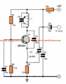
here are the circuits --(bear with me --novice at this)FP26AD6HHS9D4SR.MEDIUM FM  -BF 494 REPLACED.jpg
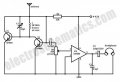
single transistor FM receiver circuit.png
 

takao21203

Joined Apr 28, 2012
3,702
These are kind of simpleton receivers.

I would make the 2x 10K network adjustable, means replace with a trimmer.

also the emitter resistor needs to be adjustable to catch a good operating point.

for the other circuit too, insert adjustable resistors in the emitter path.
 

Thread Starter

VOLTOX

Joined Jul 26, 2014
7
Thanks Takao
finally ---practical expert advice ---really appreciate your input--- please give me a corrected or modified circuit --- so I can understand clearly-where exactly to add more trim caps and variable resistors--?-
ie your version over these simple failed schematics ---which never worked in 3 months ---now I see a light --thanku so much

can u redraw me a decent working FM circuit --?-
 
Last edited:

Thread Starter

VOLTOX

Joined Jul 26, 2014
7
local FM receivers freq --

106 and 95.6 ,98 ----MHz or whateva u call them ---I,m no expert
gotta get something from this dead circuit !---tried everything ---no-one seems to want to try to construct those circuits ---to see for themselves--
appreciate your help ---
 

Thread Starter

VOLTOX

Joined Jul 26, 2014
7
BERTUS-
its central AFRICAN time zone -- Lusaka /Harare JHB---etc
or GMT ----( south CENTRAL AFRICA time zone)

I have no idea how to calculate the frequency of the simple FM
Schematics I downloaded/posted ---
maybe u can show me ---I live in the bush----again --not an expert
at all ---simply love building circuits----all home made --
trying to figure out how to downsize fotos from my huge canon file
using PHOTOBUCKET & IRFANVIEW is far too complex /annoying
and cryptic -----too user un-friendly for novices --
I only attach low pixel sketches /diagrams --where possible --
keeping it simple -----
thanks ----- :confused: VOLTOX
 

KabulDubai

Joined Jul 19, 2014
11
il est une petite FM radio microphone qui vous peux acheter a partir une magasin et copie leur components fixer de interiore de noire microphone avec rouge boutton et une droit longuer wire.

Google Translate:

it is a small FM radio microphone which you can buy from a store and copy their components fix interior black microphone with red button and right length wire.
 
Last edited by a moderator:

KabulDubai

Joined Jul 19, 2014
11
I am a software engineer in computer science and just graduated in my 40's age and when I was 12 years old I had this small FM radio microphone which I bought it in a ship named DWARKA(Indian ship) travelled from Muscat to Karachi and it's packing had a same prototype of how to assemble this by components which I saw on top of your replies which resembles exactly the way it was in 1982.
 

Thread Starter

VOLTOX

Joined Jul 26, 2014
7
Many thanks --Kabuldubai---

the reality is that to build my own FM radio means a learning leap---copying a commercially purchased working radio is meaningless--
if u can draw /sketch a working picture of the circuits I attempted and failed --it would
immediately expose my mistakes ---please try
regards ----
voltox --(cannot buy much in the bush )
 

Thread Starter

VOLTOX

Joined Jul 26, 2014
7
followed --TAKAO ,s advice ---
replaced all the 10k train /emitter & resistors with varistors --2k --20k and
5k -10k resistors ----nothing happens --same old hum from 10 watt amp --
extended antenna every which way ---changed both coils for 4 --6 turns diff thickness
gauge copper enamelled wire ---
also referred to the online books ww mikroe BERTUS referred to
--restructured the entire circuits ---
nothing but a persistent soft hum ---no frequency change noises when the trim cap 22 pf is adjusted ---
so very frustrating ----this FM nightmare will only end if someone posts a simple WORKING SCHEMATIC --- with both or single BF 494 transistors--( do not have BF 199,s---)-----my cheapo Chinese FM receiver literally blasts out all 7 FM stations
----& it consists of ONLY ONE huge IC ---SO its inner workings are hidden --
something is very wrong ---but what ?
 

takao21203

Joined Apr 28, 2012
3,702
I have built FM transmitters with plain 2n3904.

Maybe your transistors are "gone"?

Without a transistor tester it can be a nightmare to build circuits.

These Simpleton circuits react on a lot of things you may not guess such as wire lengths, humidity, the kind of PCB you use, power supply, and so on.

Did you solder them "ugly bug", or "through hole"? Or worse, trying to breadboard them?

There are always factors even experts dont see or dont think of but it's not alchemy. You go through the usual list of suspects, then see if you can see *any* change.

And for a forum thread, give all possible information: what power supply, what voltage, how built, parts list, schematic, modificatios, observations.

Then in little time the reason for failure is found.
 

alfacliff

Joined Dec 13, 2013
2,458
there are some simple rado plans in Dave's site, makeradio.com.
those one and two transistor fm radios use "slope detection" or tuning the radio on one side of the station and using the selectivity of the reciever to detect am.
 

alfacliff

Joined Dec 13, 2013
2,458
that first diagram is of a hetrodyne oacilator, no help at all unless you have an fm if detector attached. there are some simple circuits similar to regenerative recievers for fm on line, possably at "makeradio.com"
 
Top