Simple circuit to implement a function in my car with a pulse

Thread Starter

monteiro

Joined Feb 5, 2018
6
Hello everyone, could someone help me with a simple circuit I need to implement in order to add a function in my car. What I need to do it very simple but I am struggling to find out which component/IC could solve it.

Once I press a button in the dashboard of my car, I need to activate or deactivate a transistor, to turn ON/OFF another circuit.

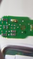
After opening the dashboard of my car, I found the following circuit attached in this thread.


How the circuit works:

Pin 8 has constanlty 5 volts and if I press the "force sensitive resistor" it sends a pulse of 40mA to somewhere and it does something. (the full PCB is basically 3 times the same circuit. Lock/unlock doors, hazard lights, and one third button that is not being used and I will add a function - OBD system)

Pin 17 - it has 12 Volts only when the button is "ON", as I already tested the whole circuit to check what is going on, after pressing the button, other circuit in the car sends 12V to the pin 17 to indicate the switch is ON.

My question: which IC / circuit / component, could give me a logic state "zero" or "one" once a pulse is sent or perceived? It has to be: I press once, and a transistor is activated, I press again, and it switches it off.

Kind Regards,
Guilherme Monteiro
 

Attachments

wayneh

Joined Sep 9, 2010
17,496
It's hard for me to understand what you really need. It sounds like a simple on/off toggle switch would do the job and you wouldn't need the transistor unless the current you are switching is more than the few amps that a cheap toggle switch can handle. If you really need a circuit to that switches state when you push a pushbutton, that's doable too. How much current do you need at the output?
 

Thread Starter

monteiro

Joined Feb 5, 2018
6
It's hard for me to understand what you really need. It sounds like a simple on/off toggle switch would do the job and you wouldn't need the transistor unless the current you are switching is more than the few amps that a cheap toggle switch can handle. If you really need a circuit to that switches state when you push a pushbutton, that's doable too. How much current do you need at the output?
Hello Wayneh,

the other circuit I will control consume 50mA. Thanks for your reply
 

Thread Starter

monteiro

Joined Feb 5, 2018
6
I think I forgot to mention: I want to use the current circuit to implement this idea. I will not add a switch, I will basically connect some wires in the PCB to make it work. I would like a circuit where I connect in the PINS 8 and 17 to do the job. Sorry, I was not clear
 

wayneh

Joined Sep 9, 2010
17,496
Let me see if I understand.

You have an unused pushbutton on your dash and you want to use it to turn on an OBD device which requires 12V and 50mA. You want the button to toggle the power on/off to the OBD (and an indicator LED?). Is this all correct?

Do you have any experience with microprocessors? I'm not saying you have to use one, but it would solve some of the problems. One big problem is that a switch must be debounced to eliminate the many make-break changes that happen as you depress it. Another problem is the latch function.
 

Thread Starter

monteiro

Joined Feb 5, 2018
6
That is correct, I have an unused push-button and I want to use it to turn on and off my OBD. It is 12V and 50mA. and the idea is to use the function in the PCB that is not being used. I have attached a photo of the circuit. every time I push the button, it generates 40mA of current.

I have no experience with microprocessors. I have an understanding of electronics, basic components and logic doors, and IC only
 

Attachments

crutschow

Joined Mar 14, 2008
34,285
You could likely use a toggle flip-flop circuit such as below:
The Q flip-flop output alternately goes high and low with each time the PB is pressed.
Note that power (the same power as to the PB) and ground must be supplied to the FF (not shown).
Relay is optional.
All unused FF inputs (not outputs) must be also connected to ground.

upload_2018-2-5_14-40-15.png
 

AnalogKid

Joined Aug 1, 2013
10,987
The pc board item looks like the landing pad for a conductive rubber key, not a "force sense resistor". It would help greatly if you would share more (*all*) of the schematic. Trying to design an interface for a resistor that is in series with something unknown and invisible is ... difficult.

The schematic shows only 5 V somewhere in the switch circuit, but post #6 mentions 12 V. Does the circuit you want to control run on 5 V or 12 V?

ak
 

Thread Starter

monteiro

Joined Feb 5, 2018
6
Hello guys, thanks everyone for the replies so far. Very appreciated

I think the correct term is "conductive rubber key" I confess I did not know the name of this type of switch and I had to google it and I thought it was that name I wrote initially.

@AnalogKid the whole PCB is exactly 3 times that initial circuit I attached. It is a repetition I attached the rest of the diagram I have done using a online platform "EASY EDA"

Unfortunately I cannot access the rest of the circuit as it goes far deep inside the dashboard. What I did was measure the voltage values in the pins with different settings (lights on, just car's key, and everything running)

The circuit I want to control runs with 12V
 

Attachments

Top