 Facebook
 Google
 GitHub
 Linkedin
Hello all,
I hope everyone is well and I thank you in advance for your assistance.
I am a newbie electronics enthusiast and have created a simple circuit which simply lights an LED when the gate in our yard is closed, but I wish to make it a little better and I was hoping you could help me.
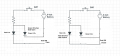
The existing circuit is this. I have a small board containing an LED, a resistor and a button. This is wired up to 50' of (16 gauge I think) solid core wire [telephone wire] this is powered with a 9v battery. The telephone wire is connected to the gate and the latch. When the gate is closed and the button is pushed, the LED lights up. So, this works as intended but I am desiring something a little more....
I want to have a 2nd LED circuit in this that lights up when the gate is open (the existing circuit is open). I hope this makes sense so far.
I desire 1 of 2 outcomes ... 1st is button gets pressed and the gate outside is closed = green light on (existing LED) ... the 2nd is button gets pressed and the gate outside is open, a red LED turns on (new circuit I don't know how to create).
Here is the existing circuit .

I feel like I need to create another circuit with the other LED that essentially shorts to ground when the existing circuit is closed. I just don't know how to create this. Any advice would be helpful. Thanks in advance.
Nathan
I hope everyone is well and I thank you in advance for your assistance.
I am a newbie electronics enthusiast and have created a simple circuit which simply lights an LED when the gate in our yard is closed, but I wish to make it a little better and I was hoping you could help me.
The existing circuit is this. I have a small board containing an LED, a resistor and a button. This is wired up to 50' of (16 gauge I think) solid core wire [telephone wire] this is powered with a 9v battery. The telephone wire is connected to the gate and the latch. When the gate is closed and the button is pushed, the LED lights up. So, this works as intended but I am desiring something a little more....
I want to have a 2nd LED circuit in this that lights up when the gate is open (the existing circuit is open). I hope this makes sense so far.
I desire 1 of 2 outcomes ... 1st is button gets pressed and the gate outside is closed = green light on (existing LED) ... the 2nd is button gets pressed and the gate outside is open, a red LED turns on (new circuit I don't know how to create).
Here is the existing circuit .
I feel like I need to create another circuit with the other LED that essentially shorts to ground when the existing circuit is closed. I just don't know how to create this. Any advice would be helpful. Thanks in advance.
Nathan

")


