Facebook
 Google
 GitHub
 Linkedin
Back in the 80's if you wanted to build a power supply you had to get a transformer, diodes, and a large capacitor. It also meant people new to electronics and electricity had to build a project using line voltage, which can be hazardous if you make a mistake.
Wall Warts
During the 90's wall wart's started becoming common. If you don't know what a wall wart is, think of a power supply box that plugs into outlet directly. They can be awkward, but more importantly, they are extremely safe to use. Nowdays you can buy pretty much what you need in the form of voltage and current. Some of them can have some pretty sophisticated circuitry to handle much higher currents than the older days.
A word to the wise though, they come in all flavors, and I do mean all. You can buy a simple AC wall wart, basically nothing but a simple transformer in the wall.
Most are simple DC power supplies with no regulation. You can usually find the specs on the case. Pay special attention to polarity, as there are no standards concerning any of these devices. As a general rule of thumb they also do not use a ground, though there are exceptions to this. It is highly unusual for ground to be connected to one of the power supply leads, though again, you can find a few exceptions.
I'm going to assume a simple DC model, or a switching unit that is highly regulated. The simple units will have non-replaceable fuses inside, if you blow them you are expected to throw them away. The unregulated models do not have stable DC voltages either, a 12VDC 1A can have as much as 18VDC out with no load, and it can be worse. You will need to check this before you use it.
To make a modern bench supply with one is simplicity itself. There are families of 3 terminal regulator chips out there, very inexpensive, very effective, and very old. You can buy many of them from Radio Shack, they are that common.
The best range in wall warts to go for is a 1A unit, 15-40VDC. Prices vary hugely, I paid under $6 for a 24VDC 1.3A switching unit. Digikey had them for under $20. It really does pay to shop for these units, and local stores can have some unexpected bargains.
Enclosures (Boxes)
This is more important than you might think, though not critical. A metal case is always to be preferred, since it is unlikely you will melt it. Most simple power supplies generate heat, sometimes lots of it. If you do decide to use a plastic box be sure to keep the heat generating components away from the plastic.
Be sure to get a box big enough to hold everything. Using a wall wart dramatically reduces the size a box needs to be, but there will be some circuitry inside, knobs on the outside, and possibly more. A simple sketch of the layout before you start buying parts and cutting holes will save you a lot of heartache.
It is worth buying a jack that matching the plug on your wall wart. This is because you don't want the wires to wear out from when you store the unit, unless you are one of the few who will have a permanent bench setup. Most of us don't.
Regulators
This is the heart of the power supply. Like I said earlier, the job is made a lot easier with modern regulators. I highly recommend the LM317. It can be used in the following schematic.

This setup will support up to 1.5A, with proper heat sinking. The LM317 can adjust between 1.25V to 37V, do not exceed 40 V on the input.
Heat Sinking
Whatever you use for the regulator, unless you are using very small currents, it will get hot. Sometimes extremely hot. Hot enough to melt plastic, this was what I was warning against earlier. Place the heat sink where it can have air flowing over it. If you are planing on using maximum currents you might even consider adding a small fan.
I would consider a heat sink an absolute necessity, but don't over think this one too much. Just plan on having one (it can be as simple as a thick chunk of metal) and allow fresh air to reach it.
Fuses
Even though the wall wart likely has a fuse, odds are it is not replaceable. This means it is a really good idea to include a simple fuse, possibly with a fuse receptacle on the outside of the box, though it can be as simple as an inline fuse inside the box. Either way, I highly recommend using one.
This is optional, but I recommend installing a simple panel meter. The one I built has a 15V with a 15KΩ impedance, I added another 15KΩ resistor and switch to create a X2 scale. Radio Shack still sells the one I used.

They are pretty common from electronic outlets, you can easily beat the price.
Other Features
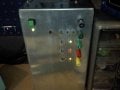
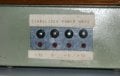
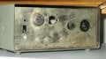
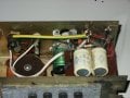
You'll note I haven't mentioned any other features. This because I wanted to keep this project simple. My unit has basic banana jacks, a meter, and a power indicator. It started off as an AC powered unit using a transformer (it was built in the 80's), I'm adding a wall wart to boost its current output. I'm also keeping the transformer as a secondary internal power supply, the wall wart jack I bought has an internal switch.
Wall Warts
During the 90's wall wart's started becoming common. If you don't know what a wall wart is, think of a power supply box that plugs into outlet directly. They can be awkward, but more importantly, they are extremely safe to use. Nowdays you can buy pretty much what you need in the form of voltage and current. Some of them can have some pretty sophisticated circuitry to handle much higher currents than the older days.
A word to the wise though, they come in all flavors, and I do mean all. You can buy a simple AC wall wart, basically nothing but a simple transformer in the wall.
Most are simple DC power supplies with no regulation. You can usually find the specs on the case. Pay special attention to polarity, as there are no standards concerning any of these devices. As a general rule of thumb they also do not use a ground, though there are exceptions to this. It is highly unusual for ground to be connected to one of the power supply leads, though again, you can find a few exceptions.
I'm going to assume a simple DC model, or a switching unit that is highly regulated. The simple units will have non-replaceable fuses inside, if you blow them you are expected to throw them away. The unregulated models do not have stable DC voltages either, a 12VDC 1A can have as much as 18VDC out with no load, and it can be worse. You will need to check this before you use it.
To make a modern bench supply with one is simplicity itself. There are families of 3 terminal regulator chips out there, very inexpensive, very effective, and very old. You can buy many of them from Radio Shack, they are that common.
The best range in wall warts to go for is a 1A unit, 15-40VDC. Prices vary hugely, I paid under $6 for a 24VDC 1.3A switching unit. Digikey had them for under $20. It really does pay to shop for these units, and local stores can have some unexpected bargains.
Enclosures (Boxes)
This is more important than you might think, though not critical. A metal case is always to be preferred, since it is unlikely you will melt it. Most simple power supplies generate heat, sometimes lots of it. If you do decide to use a plastic box be sure to keep the heat generating components away from the plastic.
Be sure to get a box big enough to hold everything. Using a wall wart dramatically reduces the size a box needs to be, but there will be some circuitry inside, knobs on the outside, and possibly more. A simple sketch of the layout before you start buying parts and cutting holes will save you a lot of heartache.
It is worth buying a jack that matching the plug on your wall wart. This is because you don't want the wires to wear out from when you store the unit, unless you are one of the few who will have a permanent bench setup. Most of us don't.
Regulators
This is the heart of the power supply. Like I said earlier, the job is made a lot easier with modern regulators. I highly recommend the LM317. It can be used in the following schematic.
This setup will support up to 1.5A, with proper heat sinking. The LM317 can adjust between 1.25V to 37V, do not exceed 40 V on the input.
Heat Sinking
Whatever you use for the regulator, unless you are using very small currents, it will get hot. Sometimes extremely hot. Hot enough to melt plastic, this was what I was warning against earlier. Place the heat sink where it can have air flowing over it. If you are planing on using maximum currents you might even consider adding a small fan.
I would consider a heat sink an absolute necessity, but don't over think this one too much. Just plan on having one (it can be as simple as a thick chunk of metal) and allow fresh air to reach it.
Fuses
Even though the wall wart likely has a fuse, odds are it is not replaceable. This means it is a really good idea to include a simple fuse, possibly with a fuse receptacle on the outside of the box, though it can be as simple as an inline fuse inside the box. Either way, I highly recommend using one.
Voltmeter
This is optional, but I recommend installing a simple panel meter. The one I built has a 15V with a 15KΩ impedance, I added another 15KΩ resistor and switch to create a X2 scale. Radio Shack still sells the one I used.
They are pretty common from electronic outlets, you can easily beat the price.
Other Features
You'll note I haven't mentioned any other features. This because I wanted to keep this project simple. My unit has basic banana jacks, a meter, and a power indicator. It started off as an AC powered unit using a transformer (it was built in the 80's), I'm adding a wall wart to boost its current output. I'm also keeping the transformer as a secondary internal power supply, the wall wart jack I bought has an internal switch.
Last edited: