Signal Generator with 20Vpp output (from 0V to 20V)

Irving

Joined Jan 30, 2016
5,195
Better to find an opamp in a DIP package that can easily be soldered on some stripboard. What frequency range, and only sine waves or others as well?
A sine wave of 200KHz.
Hmmm, finding a PDIP-cased product with a near-0v input/output capability, >24v supply and a gain-bandwidth of >2MHz is proving tricky. Maybe better to use a SOIC or SOT23 cevice on stilts or a carrier. The AD820 chip is £5.30 at RS or <£3 from eBay via China and the SOIC-DIP8 carrier is <£1.50 for 4 on eBay
 

Thread Starter

Martino Chiro

Joined May 1, 2015
128
Hmmm, finding a PDIP-cased product with a near-0v input/output capability, >24v supply and a gain-bandwidth of >2MHz is proving tricky. Maybe better to use a SOIC or SOT23 cevice on stilts or a carrier. The AD820 chip is £5.30 at RS or <£3 from eBay via China and the SOIC-DIP8 carrier is <£1.50 for 4 on eBay
Today i will place on order with some AD820 and try the circuit proposed.
 

DickCappels

Joined Aug 21, 2008
10,662
For the most part, no. The two are very different and whether they appear to be the same depends on expectations for offset voltage, output voltage range, and frequency response to name the major differences.
 

Thread Starter

Martino Chiro

Joined May 1, 2015
128
If i replace the AD820 with LM358 i will get the same results ?
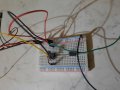
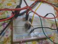
I apologize for the delay. The breadboard with the AD820 is done (not pretty to look at, cause too much haste),
and i applied a 10Vpp sine wave. The output (with no load, only the probe of the scope) shows a 20Vpp sine wave (the power supply was setup to 25V). As expected by your simulation.
The frequency was 1KHz then increased to 2KHz. The output was always 20Vpp with a sine wave shape.
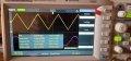
For curiosity a increased the frequency, and at 100KHz i get a quasi triangular shape in output, and a Vpp of 15,2V
also if the input (violet trace) is still 10Vpp sine wave, as the case with 2 KHz input frequency.
 

Attachments

BobTPH

Joined Jun 5, 2013
11,618
The slew rate is the max speed at which the output can change. The slew rate of your opamp is 3V/usec.

A sine wave has to go from 0 to max in half a period. At 100KHz the period is 10 usec, half is 5 usec.

So at 3V / usec, the max output voltage over a half a period is 15V, which is exactly what you are seeing.

And when the voltage is increasing at the max slew rate, it will make a triangle, since it rises at a constant rate, which is also what you are seeing.
 

DickCappels

Joined Aug 21, 2008
10,662
Back in the day when I was responsible for making circuits work in production, in my small tool kit I kept a collection of opamps. Sometimes swapping out an opamp from my kit for one in the product made the difference between (for example) a mirror slamming itself against stops and smoothy moving into position. In those days (of a start-up) a day analyzing the circuit might have cost the entire contract. There is a lot of variation among opamps.
 

Thread Starter

Martino Chiro

Joined May 1, 2015
128
Back in the day when I was responsible for making circuits work in production, in my small tool kit I kept a collection of opamps. Sometimes swapping out an opamp from my kit for one in the product made the difference between (for example) a mirror slamming itself against stops and smoothy moving into position. In those days (of a start-up) a day analyzing the circuit might have cost the entire contract. There is a lot of variation among opamps.
Thank You Dick, i think to use a LM7171 to see the difference. In order to get a better understanding of what happen. The LM7171 is more expensive of the AD820 but i am curious to see the wave shapes on the scope.
 

Thread Starter

Martino Chiro

Joined May 1, 2015
128
Thank You Dick, i think to use a LM7171 to see the difference. In order to get a better understanding of what happen. The LM7171 is more expensive of the AD820 but i am curious to see the wave shapes on the scope.
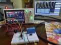
Sorry for the delay. I get the LM7171 and a breakout 8pin board to fit the SOIC in a breadboard, in place of the AD820 (with 24V of power supply). The circuit is the same proposed by Irving in #32 I added only a 100nF on the supply of the op amp.
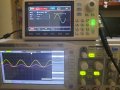
But, the result is not good: the output is more or less the half of the input signal: the picture here show the input (Yellow) and output (violet) signals. The result is the same ad 24V or 12V and at 10KHz or 100KHz.
What can be the cause ?
 

Attachments

Top