 Facebook
 Google
 GitHub
 Linkedin
Hi All, I'm pretty new to this forum, so be gentle.
I have what is probably a very simple application for most of you. I'm starting to build up a fixed dust collection system for my wood shop. My intention is to trigger the dust collector from micro switches on the blast gates.
From what I've read elsewhere, it may be a good idea to delay the shutoff of the DC to reduce the number of starts of the motor. I am thinking 3 to 5 minutes would be about right. That way if I work at one machine, move directly to another and open a different blast gate, the DC just keeps running, and shuts off a bit later when I'm truly done with it for a while.
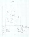
So, the first thing that came to mind was to add a circuit using a 555 IC. I attached a first draft of a circuit, based on others I've seen online and modified to energize the relay all the time that one of the switches is on. Am I close with this? I'm not very experienced with electronics, but know the basics. And not much experience with the 555 other than playing with a few circuits on a breadboard years ago. (And now that I write that I realize that I should just hook this up and try).
I have an old wall wart with 9V output that I think I can use for the supply. The switches in the lower left would be a few switches to start with, and eventually up to 11 or 12, but always wired in parallel so any one of the switches can close the circuit. The relay shown at lower right will actually be a solid state relay; 3-32VDC in, 24-380VAC load. But I didn't know what the schematic symbol was, so... I think I've drawn the symbol for a regular coil type relay.
Other example circuits I've seen include a diode across the relay inputs - I don't quite remember the purpose... something about a current being induced when the input to the relay is shut off. But in the case of a solid state relay, this is probably not needed, right?
Also, I'm not sure of the need for a diode on the output of the 555. Not sure what the chances are of current flowing back into that pin and wrecking it. But it also shouldn't hurt to have it there I think.
Last question is: Does this make sense to use a 555? 5 minutes is a pretty long delay compared to examples I've seen. Playing around with the C1/R1 combinations, I'm getting values like 10 uF / 27 Mohms, or 5454 uF (5.4 millifarads?) and 50 kohms. I haven't shopped around yet to see if those are wild values that will be hard to find. Ideally I'd like to be able to use a pot to vary the resisitance to adjust the delay time.
Or is there a reason it would be better to use a microcontroller, like an Arduino Nano?
Sorry for the rambling post... and thanks in advance for any help!
Keith
I have what is probably a very simple application for most of you. I'm starting to build up a fixed dust collection system for my wood shop. My intention is to trigger the dust collector from micro switches on the blast gates.
From what I've read elsewhere, it may be a good idea to delay the shutoff of the DC to reduce the number of starts of the motor. I am thinking 3 to 5 minutes would be about right. That way if I work at one machine, move directly to another and open a different blast gate, the DC just keeps running, and shuts off a bit later when I'm truly done with it for a while.
So, the first thing that came to mind was to add a circuit using a 555 IC. I attached a first draft of a circuit, based on others I've seen online and modified to energize the relay all the time that one of the switches is on. Am I close with this? I'm not very experienced with electronics, but know the basics. And not much experience with the 555 other than playing with a few circuits on a breadboard years ago. (And now that I write that I realize that I should just hook this up and try).
I have an old wall wart with 9V output that I think I can use for the supply. The switches in the lower left would be a few switches to start with, and eventually up to 11 or 12, but always wired in parallel so any one of the switches can close the circuit. The relay shown at lower right will actually be a solid state relay; 3-32VDC in, 24-380VAC load. But I didn't know what the schematic symbol was, so... I think I've drawn the symbol for a regular coil type relay.
Other example circuits I've seen include a diode across the relay inputs - I don't quite remember the purpose... something about a current being induced when the input to the relay is shut off. But in the case of a solid state relay, this is probably not needed, right?
Also, I'm not sure of the need for a diode on the output of the 555. Not sure what the chances are of current flowing back into that pin and wrecking it. But it also shouldn't hurt to have it there I think.
Last question is: Does this make sense to use a 555? 5 minutes is a pretty long delay compared to examples I've seen. Playing around with the C1/R1 combinations, I'm getting values like 10 uF / 27 Mohms, or 5454 uF (5.4 millifarads?) and 50 kohms. I haven't shopped around yet to see if those are wild values that will be hard to find. Ideally I'd like to be able to use a pot to vary the resisitance to adjust the delay time.
Or is there a reason it would be better to use a microcontroller, like an Arduino Nano?
Sorry for the rambling post... and thanks in advance for any help!
Keith
Attachments
-
 192.3 KB Views: 16


