Current sensor that will shut off power to a small 2 amp discharge pump.

Thread Starter

JoeJames

Joined Feb 23, 2023
15
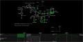
Does anyone have any ideas or thought on how I might create arduino based device that will sense when a small pump begins to cavitate while pumping down a small basin? The idea is to start pumping down an 80 gallon tank and walk away and do other things. When the pump starts cavitating the current sensor will detect the amp draw decline (because the pump is no longer under load when all the water is pumped out) and trip a relay switch that shuts the pump off automaticly. Does such a device exist already? Is this something that can be built using arduino parts?
 

Thread Starter

JoeJames

Joined Feb 23, 2023
15
It
What is the lift?
It's a 1/10 hp 1.8 amp pump. Pretty small pump. Used to pump down water in an 60 or 80 gallon water heater when preparing to change it out for a new water heater. I want to be able to walk away from it while it's doing it's job and let the drop in load (when it's empty and cavitating to shut if off)
 

Thread Starter

JoeJames

Joined Feb 23, 2023
15
What is the lift?
What I would do is drop one connection 3/4 washing machine style hose down to the bottom of the waterheater (through the pressure relief valve) so that would be maybe 5' max of lift. Then the other side of the hose falls away to the nearest bathroom shower drain or out a window, what ever is available.
 

Thread Starter

JoeJames

Joined Feb 23, 2023
15
The reason for this is when changing out a water heater often the hose bib at the bottom is fouled and wont drain, or it will drain but slowely and it can get real messy with sludge if having to wrench the hose bib off do get the drain to flow. Going through the pressure relief with a small pump allows to drain the tank, making it nice and light to get it out of the house with the added bennifet of not making a mess. The current sensing switch is a nice feature if your busy doing other things while the old tank is pumping down... maybe not have to sit there and babysit it (?)
 
The LM358 amplifies the 0.47 ohm shunt voltage (about 1V) to about 10V, the rectifier with cap stores the measured current for a few sine periods, the schmitt trigger switches relay on/off according measured current.

To start the pump a pressing the PB button is needed. If the current is high enough the mosfet is switched On, so after releasing the PB the relay coil stays energised. If the current is too low after releasing the BP the coil doesn’t stay energised.

The 10k pot sets the current trip-point.

IMG_1616.jpeg
 
Last edited:

tonyStewart

Joined May 8, 2012
231
Similar to Michal's but using 1/4W R and no Pot needed. 12V power on starts relay. If water is empty , current drops and relay trips in about 1/3 s. Hysteresis using resistor from FET drain. Any old signal diodes for rect. and flyback.
Reset switch is optional since 12V power switch does the same thing. Press switch or change any value you want. https://tinyurl.com/25hpkz25

1740366220340.png

Import aspects of the design is the LM358 must not exceed -0.3V on any input so I reduced the shunt Rs since pumps are known to surge +500% on startup or -0.3V , so I added 10k series to Vin+ this may need Schottky negative clamp. It must verify not to exceed under any condition of random phase start.

If 50 mohm is not avail. cheap then gang two 100 mohm
 

Attachments

Last edited:

tonyStewart

Joined May 8, 2012
231
My uncertainty is the peak reactive current with no pump load may be too high relative to with load. If the motor inductance is 0.5H then increase 1k to 3.3k to reduce gain or use a 5k trimpot.
 
Last edited:

Thread Starter

JoeJames

Joined Feb 23, 2023
15
The LM358 amplifies the 0.47 ohm shunt voltage, the rectifier with cap stores the measured current for about few sine periods, the schmitt trigger switches relay on/off according measured current.

To start the pump a pressing the PB button is needed. If the current is high enough the mosfet is switched On, so after releasing the PB the relay coil stays energised. If the current is too low after releasing the BP the coil doesn’t stay energised.

The 10k pot sets the current trip-point.

View attachment 343108
Thank you! I will study this today. It just occured to me that when a pump cavitates it also speeds up under no load conditions. Could a small device that measures rotation speed also work?
 
Thank you! I will study this today. It just occured to me that when a pump cavitates it also speeds up under no load conditions. Could a small device that measures rotation speed also work?
Turning on and off according speed is possible also. You need a tachometer, or small dc motor connected to shaft. Best is the one outputting <5V when pump is loaded and >5V when pump is unloaded, so you don’t need an amplifier nor rectifier. Just a window-comparator and Latch on its output.

Window-comparator switching levels:
Tacho 0-1V …. Latch Off
Tacho 1-5V …Latch On
Tacho 5-10V…Latch Off
 
Last edited:

Alec_t

Joined Sep 17, 2013
15,101
What I would do is drop one connection 3/4 washing machine style hose down to the bottom of the waterheater (through the pressure relief valve) so that would be maybe 5' max of lift. Then the other side of the hose falls away to the nearest bathroom shower drain
Couldn't you just siphon the water out?
 

Thread Starter

JoeJames

Joined Feb 23, 2023
15
The LM358 amplifies the 0.47 ohm shunt voltage (about 1V) to about 10V, the rectifier with cap stores the measured current for a few sine periods, the schmitt trigger switches relay on/off according measured current.

To start the pump a pressing the PB button is needed. If the current is high enough the mosfet is switched On, so after releasing the PB the relay coil stays energised. If the current is too low after releasing the BP the coil doesn’t stay energised.

The 10k pot sets the current trip-point.

View attachment 343108
Thank you! Do you have a modular Arduino version of this set up?
 
Thank you! Do you have a modular Arduino version of this set up?
I don’t think the Arduino is more useful for this kind of application.

If still like the Arduino, measure the 0.47 shunt voltage with analog pin to get the current.
Connect the mosfet for driving a relay coil to dig. output pin.
Connect a button to a dig. input.

After pressing a button try to switch the relay for a 2 seconds. If the current is high enough let the relay On.
Once you measure low current (pump unloaded) switch the relay Off.
 

AnalogKid

Joined Aug 1, 2013
12,043
Couldn't you just siphon the water out?
That can take hours. And not just any old DIY hours, them are plumber-by-the-hour hours.

I strongly recommend an isolated current sensor (called a current transformer) approach. There are industrial, adjustable current-sense relays you can buy, but $$$.

https://images.search.yahoo.com/sea...-?p=current+sense+relay&fr2=piv-web&fr=fp-top

Actually, this isn't a bad idea for a product. 6' industrial extension cord, but with a box at the end instead of just a socket. The box has the sense transformer, an adjustable comparator circuit, and an output relay; and the side of the box has a standard socket. Plug in the pump and adjust the dial. Bonus points for a flashing LED and a small piezo beeper to indicate the relay has tripped. If you're lucky, someone already has produced this, and someone around here knows where to get one.

ak
 
Last edited:
Top