Helping people on this site requires some commitment of time by the those asking and those supplying assistance. Last week you posted a circuit asking for help and you got 10 responses. You didn't "Like" any of the posts nor did you bother to acknowledge any of the responses. You posted and promptly disappeared. I suggest you close that open loop first so we can have some confidence we are not wasting our time with this problem.
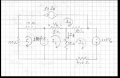
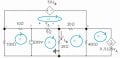
Just in case this problem gets worked on, I marked up the schematic with some mesh and node numbering. If everybody who works on it would use these designations it will be easier to talk about it and to compare results:
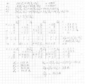
You mentioned KVL so I solved the circuit with mesh analysis and I believe my solutiion is correct; given that:
Your answers for I phi and V delta are correct: 3.8A and 147V, I can't say about the mesh currents because I can't follow your labeling. Only one of my 4 mesh currents match yours; maybe your currents are branch currents - I don't know.
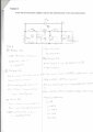
Your work is hard to follow. It is not neccesary or I believe helpful to mark currents in every branch. It creates quite a mess. And your system seems a bit confused. For example at the top right in what you label mesh #2 you show it's current as I1. In a number of places the current notations don't match the mesh number. On the bottom you have 3 current additions to describe what ought to be just one. The current at the bottom of what you label mesh #1 should just be I1, but you have I4+I1-I3. ???
Annotating the schematic as the Electrician did is all you need. My suggestion is to always draw the loop currents in the same direction ( I prefer clockwise - if you live in the Southern Hemisphere perhaps you prefer counter clockwise ). Don't try to get the current directions to match the sense of already notated currents. Stick to your routine. Then you don't have to think about signs, it becomes very automatic when you transcribe the loops into equations. The mesh you are currently in always has a positive current sense and adjacent loop currents are always negative. For example, while doing mesh 3 (per Electricians annotation) you would write 5(I3-I1) for the voltage across the 5 ohm. You don't even have to look at the I4 direction if you follow my rule. The less juggling of signs in your head the less chance of an error. After you have all the mesh currents you can easily find the currents and voltages you are interested in finding.
By the way, I changed the dependent current source on the right into the Thevenin equivalent so I had only 4 meshes to solve.
So you still need to track the power flow to answer the question. How did that go?
And can you clearly label where your I1,I2,I3 are on the schematic?
My apology to the Electrician: I had already completed the work with a different mesh numbering scheme.
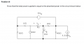
I Just Used KCL to Find Current Through Each Element and then Used Kvl Equations at the labeled Regions to find the Current,But My Problem is with the Finding Power And assuming Polarity.
Note:I didn't yet Take Mesh Currents or node Voltage.
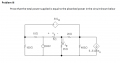
Thanks For the Effort View attachment 113670
Just in case this problem gets worked on, I marked up the schematic with some mesh and node numbering. If everybody who works on it would use these designations it will be easier to talk about it and to compare results:
My apology to the Electrician: I had already completed the work with a different mesh numbering scheme.
View attachment 113670
I used KCL to set Variables for currents through Each node then I applied KVL at Specified region to get the Currents but I have problems finding that all power = 0 and assuming right polarity View attachment 113669
Any questions about this, Mohamed? Can you explain your approach and how it differed?
But analyzing the circuit is only a prelude to a solution of your problem. Can you show how you will find the power dissipated in the resistors? And next the power delivered or absorbed by the sources?
It looks like you put a lot of effort into the analysis, and assuming you got it right for now, next you have to calculate the power in each element and equate the power delivered to the circuit and the power absorbed. You should get an equality if you did it right.
Note that the passive elements here absorb power, and at least one source delivers power to the circuit, but it is possible that a source absorbs power too. It depends highly on the correct analysis of the currents and voltages.
Try calculating the power in each element next and see what you can find out.
BTW as far as the node voltages go this is another all-integer problem
It looks like you put a lot of effort into the analysis, and assuming you got it right for now, next you have to calculate the power in each element and equate the power delivered to the circuit and the power absorbed.
His numbers are correct so far -if derived in a little unorthodox manner. Since he has shared nothing regarding his approach on tallying the power flow I have difficulty understanding why he has a problem doing that calculation or how to help him. The hardest part is done, from here it is simple multiplication of current and/or voltages and resistances - paying attention to the power sign conventions such as for the Passive Sign Convention. Somewhat tedious but simple to add them all up: P=IV, P =R*I^2 ??? The ball is in your court Mohamed.
I don't understand why anyone would spend more than 5 seconds on this. Are you really trying to show that the laws of thermodynamics might not apply? Just how exactly could the supplied power not equal the absorbed/dissipated power?

 Facebook
 Google
 GitHub
 Linkedin

 72 KB Views: 13

 ). Don't try to get the current directions to match the sense of already notated currents. Stick to your routine. Then you don't have to think about signs, it becomes very automatic when you transcribe the loops into equations. The mesh you are currently in always has a positive current sense and adjacent loop currents are always negative. For example, while doing mesh 3 (per Electricians annotation) you would write 5(I3-I1) for the voltage across the 5 ohm. You don't even have to look at the I4 direction if you follow my rule. The less juggling of signs in your head the less chance of an error. After you have all the mesh currents you can easily find the currents and voltages you are interested in finding.