seven segments display (2 digits)

Thread Starter

kyu9971

Joined Mar 28, 2015
90
Hi everyone,
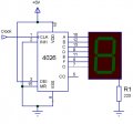
I would like to use this seven segment display but I did not understand how it works. It is a common cathode display with 11 pinouts.
pin 3 is the common digit cathode number 1 and pin 5 is the common digit cathode 2. Anyone can tell me what i can to show 2 different numbers on these digits.
For example if i need to show the number "45" how can i do it?
Thanks in advance
Screenshot_20171105-101230.jpg
 

dl324

Joined Mar 30, 2015
18,330
Seven segment displays are more typically used with counters+decoders or microcontrollers.

The display in question has shared anodes, so you need to multiplex the digits. Apply a current limited voltage to pins segments F,G,B,C (pins 12,2,10,11) and ground 3 to display a 4, then apply a current limited voltage to A,F,G,C,D (pins 8,12,2,11,9) and ground pin 5.
 

shteii01

Joined Feb 19, 2010
4,644
1. You connect Pin 3 and Pin 5 to 0 volts.
2. Since you don't need decimal point, you connect Pin 4 and Pin 6 to 0 volts.
3. You apply some voltage to remaining pins to turn the individual LED on.

The following warnings apply:

- the datasheet for the 7 segment display should tell you what voltage you need to apply

- normally people include a resistor on each led to control the current that will go through the led. Excessive current will burn out the led. Again. The datasheet will list what amount of current is acceptable.
 

LesJones

Joined Jan 8, 2017
4,511
This display is designed for multiplexed operation. The connection for each segment is connected to that segment on both digit positions . (Note the decimal points are not connected together.) You can't display both digits at the same time. (Unless they are the same digit.) To display 45 you first display the 4 in digit position 1 by driving segments B,C,F,G (To positive) and digit 1 common cathode (Negative). You then display the 5 in digit position position 2 by driving segments A,C,D,F,G (To positive) and digit 2 common cathode (Negative) Yoy arrange the circuit to switch between the two states at a frequency higher then the pesistance of vision. (Above about 100 Hz) It will then look like both the 4 an d the 5 are being displayed at the same time. This would normally be done using a microcontroller. This method reduces the number of I/O pins required on the microcontroller. You can do this with more than two digits. If you try to do this with too many digits the display will become too dim as each digit is only illuminated for a very small proportion of the time. You also need a resistor for each segment to limit the current.

Les.
 

ian field

Joined Oct 27, 2012
6,536
If i want to use this circuit for make a counter, what i need to add?View attachment 138732
Most people use separate resistors for each segment, the current shared among the segments from a common resistor will vary according to how many segments are lit. Tolerance spread on segment Vf and CMOS chip output RDSon could even result in certain combinations having segments to fail to light.

Check the decoder/driver data sheet - some have constant current or even programmable current outputs, those don't need any resistors at all.
 

LesJones

Joined Jan 8, 2017
4,511
You would need seven two input multiplexers (Probably this would be in three IC packages.) You would need an oscillator (A NE555 would do.) running at about 200 Hz. You would probably also need transistors or some driver chips as the output of the multiplexers would probably not have the drive capability to drive the LED. It would be cheaper to use non multiplexed displays or use the existing display with a microcontroller.

Les.
 

ian field

Joined Oct 27, 2012
6,536
2:1 multiplexers on the segment outputs of the two counters and logic to switch between the two digits.

You'd be better off buying a 2 digit display that didn't require multiplexing.
I was just wondering what pins 3 & 5 do on the diagram the TS posted in #1.
 

Thread Starter

kyu9971

Joined Mar 28, 2015
90
I think this is very complex for my capability.
i believe that i will go on two separate display solution as the last schematic that i posted.
 

dl324

Joined Mar 30, 2015
18,330
i believe that i will go on two separate display solution as the last schematic that i posted.
If you do that, keep in mind that the outputs of CD4026 can only source about 1 mA and that you'll probably want to use segment drivers (with current limiting resistors). Because of that, you might want to switch to common anode displays.
 

Thread Starter

kyu9971

Joined Mar 28, 2015
90
Ok thank you for the suggestions.
Can i put an uln2003 (darlignton transistor) between each display and cd 4026?
 

dl324

Joined Mar 30, 2015
18,330
Can i put an uln2003 (darlignton transistor) between each display and cd 4026?
CMOS driving TTL can be problematic. The max input current for the ULN2003 is greater than the guaranteed current CD4026 can source. It might work for some parts and not work for others.

For one off circuits, it's probably okay because you can cherry pick parts. For high volume, the design should be more conservative.
 

Thread Starter

kyu9971

Joined Mar 28, 2015
90
I seen on you tube a lot video of counter made only Cd4026 and seven segment display.
there isn't nothing driver between display and ic.
 

dl324

Joined Mar 30, 2015
18,330
I seen on you tube a lot video of counter made only Cd4026 and seven segment display.
there isn't nothing driver between display and ic.
Yet another example of the kind of crap you find on YouTube. CD4026 can't source or sink enough current to drive 7 segment displays directly.

This is what the datasheet shows for interfacing:
upload_2017-11-5_14-21-10.png

I don't see the point of integrating a 7 segment decoder with a counter if the outputs can't drive LEDs directly.

Since you're going to need two IC's per display, I would have opted for a counter and BCD to 7 segment decoder (e.g. CD4511). CD4511 is capable of sourcing up to 25mA and can drive common cathode displays directly.
 
Top