Setting up the AK8963C compass module.

Thread Starter

camerart

Joined Feb 25, 2013
3,724
After a question in another thread, regarding intermittent COMPASS results, I decided to start a new one.

How does the compass fail?
Are you using the SW or HW Spi?
A simple test could be to rotate the compass in for example 30 degrees steps and record the x, y values.
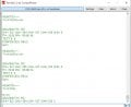
Show the compass part of the software.
Hi J and E,
When the COMPASS worked ok, including all settings and calculations, to get 0-359DEG, up until I added it into the MAIN program where it went intermittent.

When I wrote the settings, I had to choose which MODE setting to use, I chose CONTINUOUS MODE, and 100MHz.

Thinking about it, the above setting tells me that the AK8963C could be LOOPing at 100MHz, which would mean timing, and perhaps a timing error.

Today, using the MAGMASTER test rig I have with, only a dedicated COMP program on it, I'm going to first try changing to 8MHz choice and watch the DRDY. Then I'll try using the DRDY, on SINGLE MODE with a WEND WAIT, and see what happens.

EDIT: MAGMASTER HERE: https://diydrones.com/m/blogpost?id=705844:BlogPost:1676387&maxDate=2017-03-14T18:01:50.202Z
NOTE: I'm not using the suggested HMC5883L module, but the AK8963C chip independently.

Camerart.
 

Attachments

Last edited:

Thread Starter

camerart

Joined Feb 25, 2013
3,724
Try reducing the sampling rate to 100 Hz.
Hi J2,
It is already set to 100MHz, did you mean 8?

I wonder though that, if timing is the problem, then the COMP may falter, as I add CONTROLs into the program, this may happen again.

If you have the AK8963C Data sheet, and you understand the difference between the MODES, would you be good enough to outline, what each does, I can't quite follow.
C
 

jjw

Joined Dec 24, 2013
823
It is not 100MHz or 8MHz.
It is 100Hz or 8Hz.
Where is the latest working compass program?
I have some incomplete programs.
 

Thread Starter

camerart

Joined Feb 25, 2013
3,724
It is not 100MHz or 8MHz.
It is 100Hz or 8Hz.
Where is the latest working compass program?
I have some incomplete programs.
Hi J,
There is a small COMP program that was made for the MAGMASTER BIAS DATA set-up, but we've moved on from there, so maybe some PINs or other settings have been changed.

If you don't mind looking at the MAIN program, which is almost working, but has 'those' disliked comments in, I can lessen the comments and post it. For me this would be better, as adding your corrected short program into the MAIN one, is bound to cause errors.
C
 

jjw

Joined Dec 24, 2013
823
Did you say it works sometime?
I don't know what happens when there is an interrupt.
Have you tested without interrupts?
Do you get then correct angles?
 

Thread Starter

camerart

Joined Feb 25, 2013
3,724
Did you say it works sometime?
I don't know what happens when there is an interrupt.
Have you tested without interrupts?
Do you get then correct angles?
Hi J,
Yes, it mostly doesn't work, then it may start working. I can switch it off, reprogram the PIC and it still works, then stops, and won't start.

1/ I disarmed the INTERRUPT, which stalls the program.
2/ I removed the LINE0805 section, and the COMP started, then stopped. I think this was just random, but was running perfectly with the INTERRUPT. NOTE: I notice line 0429 and 0526!

When the COMP is working, apart from calibrating, it works perfectly, including the calculations and settings.
C.
 

Thread Starter

camerart

Joined Feb 25, 2013
3,724
Can you describe what you are doing with the DRDY (pin/bit)? That is, are you polling or using it as an interrupt?
Hi J2,
When I read about the MODEs in the D/S I imagined that in CONT MODE the AK8963C would SEND out it's DATA 8 or 100Hz so doesn't need DRDY. Or in SINGLE MODE it would wait till DRDY was READ, so I chose CONT and no DRDY.
C
 

jpanhalt

Joined Jan 18, 2008
11,087
My understanding of sections 6.4.3.1 and 6.4.3.2 (Continuous mode) is that DRDY (or its byte) must still be checked for reliable readings.
 

sagor

Joined Mar 10, 2019
903
C, again and again, people will tell you that in your serial UART interrupt routine, you may have more than one character in the FIFO buffer of the UART(or a second character arrives when you are processing the first). You must always check the RCIF flag bit, and if it =1, you must go back and read the second character. Only when RCIF = 0 can you safely exit the interrupt routine. RCIF can only be =0 when there are no characters left in the UART FIFO. It is a very simple "IF PIR1.RCIF =0" test to check if it is ok to exit the interrupt routine. Otherwise, you go back to the "char = RCREG" portion and process the second character.
In most cases, there will be only the one character and this will not be an issue. If you don't do this check, there is a possibility you will get the overflow error.
 

Thread Starter

camerart

Joined Feb 25, 2013
3,724
C, again and again, people will tell you that in your serial UART interrupt routine, you may have more than one character in the FIFO buffer of the UART(or a second character arrives when you are processing the first). You must always check the RCIF flag bit, and if it =1, you must go back and read the second character. Only when RCIF = 0 can you safely exit the interrupt routine. RCIF can only be =0 when there are no characters left in the UART FIFO. It is a very simple "IF PIR1.RCIF =0" test to check if it is ok to exit the interrupt routine. Otherwise, you go back to the "char = RCREG" portion and process the second character.
In most cases, there will be only the one character and this will not be an issue. If you don't do this check, there is a possibility you will get the overflow error.
Hi S,
I'll try to remember this when I address the UART GPS again, but at the moment we are talking about the AK8963C COMPASS module addressed via SPI,
Thanks
C.
 

Thread Starter

camerart

Joined Feb 25, 2013
3,724
My understanding of sections 6.4.3.1 and 6.4.3.2 (Continuous mode) is that DRDY (or its byte) must still be checked for reliable readings.
Hi J2,
I misread that, and didn't connect the DRDY, but will do.
Would it be checked by [ WEND WHILE ] ?
C.
 

jpanhalt

Joined Jan 18, 2008
11,087
I don't think you actually have to read the pin or have anything connected to it. You can alternatively read the ST1 register:
upload_2019-10-7_14-26-3.png

and test bit D0. NB: It's a read only register. In my case, I just tested the pin. Your case may be different as you may not have enough inputs on you MCU.
 

Thread Starter

camerart

Joined Feb 25, 2013
3,724
I don't think you actually have to read the pin or have anything connected to it. You can alternatively read the ST1 register:
View attachment 187504

and test bit D0. NB: It's a read only register. In my case, I just tested the pin. Your case may be different as you may not have enough inputs on you MCU.
Hi S,
I have spare PINS, is there a preference between the 2x choices?
C.
 

jpanhalt

Joined Jan 18, 2008
11,087
Functionally, reading a pin or register is the same so far as I know. Reading register ST1 (0x02) takes more steps than reading the pin. That is, it's an SPI address/read, transfer data, then read bit. The functional advantage to having a DRDY signal is when it is used as an interrupt.
 

Thread Starter

camerart

Joined Feb 25, 2013
3,724
Functionally, reading a pin or register is the same so far as I know. Reading register ST1 (0x02) takes more steps than reading the pin. That is, it's an SPI address/read, transfer data, then read bit. The functional advantage to having a DRDY signal is when it is used as an interrupt.
Hi J2,
Waiting for your reply, I came to the same conclusion, that READing the PIN takes fewer steps, so I'll add a PIN.

Is this checked by a WAIT/WEND?
C
 

jpanhalt

Joined Jan 18, 2008
11,087
Sorry, I do not do Oshonsoft. In Assembly, one would probably use a bit test on the port (btfss or btfsc = bit test register/port and skip next instruction if set/clear, respectively).

If WAIT does what I suspect, that might be equivalent to "btfss" followed immediately by a command to step back one step (i.e., keep testing the bit until it is set). That will pause everything for the time it takes for the bit to change, but that is not necessary to do. An interrupt based on the bit (say an IOC or INT pin) or a timer rollover (i.e., check once each rollover and do other things in the interim) are two of the ways to avoid that delay.

Of course, in your design, you have other interrupts working, and it is more complex.
 
Top