Setting certain bits to a word. Puzzled.

Thread Starter

HB_

Joined Jan 11, 2020
13
Hello everyone,
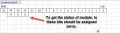
to our request the manufacturer answered with this picture. See attachment.
We are a bit puzzled by this picture, since it looks confusing for us.
As per word mapping we have to assign zeros only to bits 12,13,14. to get status word.
It is oddly enough amid other untouched bits which I suppose also have zeros by default.
I'm afraid it is not workable, since the module is not be able to recognize the command. Actually what we have at the moment.
Am I correct?
Any insights on this maatter, please.
 

Attachments

Thread Starter

HB_

Joined Jan 11, 2020
13
I'm afraid it is not workable, since the module is not be able to recognize the command. Actually what we have at the moment.
Have you read this line at my first post?

as concerned the manufacturer. Unfortunately we have no access to the respective department of software/ hardware developing and communicate via email with moonlighting students which were applied by this company as support engineers, or something like this.
 
Last edited:

ericgibbs

Joined Jan 29, 2010
18,766
hi HB,
It would help if we knew what the device is, do you have a link or part number.?
Which programming language is being used.?
E
 

atferrari

Joined Jan 6, 2004
4,764
Have you read this line at my first post?

as concerned the manufacturer. Unfortunately we have no access to the respective department of software/ hardware developing and communicate via email with moonlighting students which were applied by this company as support engineers, or something like this.
Oh I see. Sorry.
 

Thread Starter

HB_

Joined Jan 11, 2020
13
I'm afraid you won't be able to find anything in the WEB, since the term OEM supposes that, for example, the device is produced under special contract conditions which don't suppose any direct, free, wide offers for given product on the market.
Look for OEM term in the WEB.
 

jpanhalt

Joined Jan 18, 2008
11,087
...communicate via email with moonlighting students which were applied by this company as support engineers, or something like this.
Surely you can tell us the communication protocol and registers you need to read? My guess is SPI in two consecutive bytes. Maybe a "read" begins 1000xxxx (or something) followed by the address.
 

DNA Robotics

Joined Jun 13, 2014
647
Bitwise AND (&)

The bitwise AND operator in C++ is a single ampersand, &, used between two other integer expressions. Bitwise AND operates on each bit position of the surrounding expressions independently, according to this rule: if both input bits are 1, the resulting output is 1, otherwise the output is 0. Another way of expressing this is:

0 0 1 1 operand1
0 1 0 1 operand2
----------
0 0 0 1 (operand1 & operand2) - returned result

In Arduino, the type int is a
16-bit value, so using & between two int expressions causes 16
simultaneous AND operations to occur. In a code fragment like:

int a = 92; // in binary: 0000000001011100
int b= 101; // in binary: 0000000001100101
int c = a & b; // result: 0000000001000100, or 68 in decimal.
Each of the 16 bits in a and b are processed by using the bitwise AND, and all 16 resulting bits are stored in c, resulting in the value 01000100 in binary, which is 68 in decimal.

One of the most common uses of bitwise AND is to select a particular bit (or bits) from an integer value, often called masking.

In your case,
X=X & 10001111 11111111 will clear those 3 bits to zero.

Why is there no bit 5 in your control word picture?
 
Last edited:

Thread Starter

HB_

Joined Jan 11, 2020
13
Thank you, I tried masking method a few days ago. "000" amid other "1"
There wasn't any result there.
If judging on the picture, there should be only three bits affected.
What prevented them from drawing this way: "10001111 11111111" ? The history has no records.
 
Top