Servocontrol card, comparing rotary transducers

Thread Starter

Thelabg3

Joined Dec 7, 2018
2
Hello guys. Im new to the forum, and basically pretty new to this kind of electronics, but I have 10 years of experience as electrician.

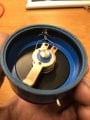
So I have this servocontrol card, that I really just want to understand what's going on with.

As you can see in the marked area on the picture, there is 2 rotary transducers (Vishay 200SF 2kΩ) going to a CA747E comparator. And as im not fully understanding comparators, I would like to know the workings of this circuit. Is it comparing the difference between the two potmeters and outputting a voltage relative to the difference between them?

https://www.vishay.com/docs/54004/rotsf.pdf - Vishay Rotary transducer
https://www.datasheets360.com/pdf/-4237304532948816104 - CA747E datasheet


Attachments

LesJones

Joined Jan 8, 2017
4,191
A comparator does compare two input voltages but it's output is not proportional to the difference. If the + input is more positive than the - input (Even if this is only a few mV) then the output will be a high logic level (Almost the positive supply voltage to the comparator positive power supply voltage.) If the + input is less positive than the - input then the output will be a logic low which is near the negative supply voltage to the comparator. The CA747 is really an operation amplifier (But it can be used as a comparator.) As the diagram is a "functional diagram" I think the CA747s are being used as op amps but the feedback resistors not shown. As the valves on the output are labled "servo valves" I think the output (flow or pressure.) is proportional to the voltage input to them. (As opposed to a solenoid valve which is either open or closed.) The potentiometers on the left side of the diagram are unusual as they have two sliders. (I have not seen one of these before They are not the same as the ones in you link as they only have one slider.) I would guess that this is part of an industrial hydraulicly powered robot.

Les.
 

MaxHeadRoom

Joined Jul 18, 2013
28,699
They look like typical proportional valves where a varying DC will move the armature to a 'proportional' position depending on the +ve or -ve voltage level on the coil.
Usually some kind of feed back is used as in the rotary pots.
In this case I would assume they are single turn?
Max.
 

Thread Starter

Thelabg3

Joined Dec 7, 2018
2
A comparator does compare two input voltages but it's output is not proportional to the difference. If the + input is more positive than the - input (Even if this is only a few mV) then the output will be a high logic level (Almost the positive supply voltage to the comparator positive power supply voltage.) If the + input is less positive than the - input then the output will be a logic low which is near the negative supply voltage to the comparator. The CA747 is really an operation amplifier (But it can be used as a comparator.) As the diagram is a "functional diagram" I think the CA747s are being used as op amps but the feedback resistors not shown. As the valves on the output are labled "servo valves" I think the output (flow or pressure.) is proportional to the voltage input to them. (As opposed to a solenoid valve which is either open or closed.) The potentiometers on the left side of the diagram are unusual as they have two sliders. (I have not seen one of these before They are not the same as the ones in you link as they only have one slider.) I would guess that this is part of an industrial hydraulicly powered robot.

Les.
Thanks for your response! So your probably correct on the CA747s being used as a op amp, instead of a comparator as I thought, because it is indeed a servo valve which is proportional to dc voltage input as Max said. And your also correct on the unusual pot's, they do have 4 pins. Have a look at the picture down below. And yes, it is part of an industrial hydraulic robot! How does the op amp treat the voltage input from the potmeters then? I've also attached some pictures of the control card. (I know, great surface finish! Holy crap :O )

They look like typical proportional valves where a varying DC will move the armature to a 'proportional' position depending on the +ve or -ve voltage level on the coil.
Usually some kind of feed back is used as in the rotary pots.
In this case I would assume they are single turn?
Max.
You are in fact completely correct on the servo valve. It is indeed moving with the varying DC, where the polarity of the voltage controls the direction of the armature. The rotary pots used is as LesJones said a 4 pin pot, and is continious, as in "infinite".
 

Attachments

LesJones

Joined Jan 8, 2017
4,191
This is a lot of guess work. I think one of the two potentiometer in the circled section is mechanically coupled to the elbow. I think the other is the operator control to set the required position I think the left hand two op amps each give an output proportional the difference in voltage between the wipers on the potentiometer that connects to it's input. In the actual circuit there will be resistors on the inputs and a resistor from the output to the - input of that op amp. I think the right hand op amp will be configured as an adder. This will give an output proportional to the difference in voltage from the potentiometers. As the aim will be to get zero output from the adder the potentiometers must work in reverse. (When one is turned clockwise the other is turned anti clockwise.) This is because to get zero output from the adder the inputs to it must be equal but opposite polarity. The potentiometers on the output of the adders will be to set the loop gain of the servo system so it responds as quickly as possible without becoming unstable. So as the arm gets close to the desired position the speed of movement will be reduced via the servo valve. I don't know if the pressure sensors are for tactile feedback or hydraulic fluid pressure sensors but they will also have an effect on the speed of movement. That is about the limit of my guess work.

Les.
 

BillB3857

Joined Feb 28, 2009
2,571
My thought on the 4th terminal of the pot is that it provides a center tap of the resistive element. Using that as one input to the op amp would result in a bi-polar output as the wiper moves from one side of center to the other. The thing that confuses me is the "continuous rotation" aspect of the pot. The photo provided in post #4 clearly shows a gap in the resisistive element. One reason for this "feature" may be to prevent internal damage in the event of overtravel of the input shaft.
"
 
Top