Series bus13a transistor voltage regulator ckt needed

Thread Starter

zorbathebutcher

Joined Jul 14, 2025
7
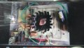
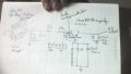
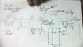
I need a diagram for a transistor series voltage regulator, using a BUS13A transistor. The voltage in is 450volt ac 100 hz. The regulated output voltage is 400v. This is for a Jadis jp80 preamp, i cannot get the info from the company. I just purchased the unit , as a tech i am rebuilding the unit , 37 years old. The regulator is not working. PLEASE HELP........
 

Thread Starter

zorbathebutcher

Joined Jul 14, 2025
7
How much current does it need?
I think it will run around 3 amps, with a 6 amp surge when charging the two,150uf 450 volt capacitors. Jadis always over rated the components. They will not give me any specs or schematic. Since i purchased the unit used the regulator was butchered and did not work, so i am lost for the proper specs. Thankyou.
 

Ian0

Joined Aug 7, 2020
13,112
I think it will run around 3 amps, with a 6 amp surge when charging the two,150uf 450 volt capacitors. Jadis always over rated the components. They will not give me any specs or schematic. Since i purchased the unit used the regulator was butchered and did not work, so i am lost for the proper specs. Thankyou.
450V rectified and smoothed is 636V
Going to need a big heatsink to dissipate 708W.
By the way, where does it get 450V AC @ 100Hz from?
 

Thread Starter

zorbathebutcher

Joined Jul 14, 2025
7
450V rectified and smoothed is 636V
Going to need a big heatsink to dissipate 708W.
By the way, where does it get 450V AC @ 100Hz from?
Here is a picture of the original regulator ckt, and a drawing of what i have, the diode are 1n4007 ??????
 

Attachments

Ian0

Joined Aug 7, 2020
13,112
The 400volt regulated supply feed 6 audio tubes. So my current rating is very high, i really have no idea of the demand.
Something like an EL34 runs at an anode current of 100mA. My guess is that it won't be more than half an amp total.
Are the zeners still intact?
 

schmitt trigger

Joined Jul 12, 2010
2,052
If the tubes are operated in class AB push pull, when one half are conducting its maximum current, the other half will be at cutoff.
Thus I agree with Ian that 1/2 amp total should be more than plenty.
 

Ian0

Joined Aug 7, 2020
13,112
I would suggest getting a 650V MOSFET in a TO247 package, because the TO247 has the same distances between pins and fixing holes as the TO3. That would allow a much larger value for the resistor currently labelled as 100Ω, but a zener between gate and source may also be required to protect the gate at the moment of switch-on.
 

Thread Starter

zorbathebutcher

Joined Jul 14, 2025
7
Something like an EL34 runs at an anode current of 100mA. My guess is that it won't be more than half an amp total.
Are the zeners still intact?
No they are 1n4007 diodes, not zeners. So i agree with the half amp total and need the proper zeners and resistor values. The person i purchased the jadis jp80 from serviced the unit in Montreal, and i have no idea what they were thinking. So i contacted Jadis , they give out no tech info. I just would like to make this unit back to good reliable specs. js
 

Ian0

Joined Aug 7, 2020
13,112
The four diodes in series connected to the transistor base SHOULD be zeners, regardless of what has been fitted,
 

Bordodynov

Joined May 20, 2015
3,430
So why have four reverse-biased diodes in series?
Perhaps the diodes in this place are not 1N4007, but some 100 volt diodes, and they can behave like zener diodes. I think it's a protection against short pulses in the network during a thunderstorm. There are suppressors now, and I recommend installing them.
 

Ian0

Joined Aug 7, 2020
13,112
Perhaps the diodes in this place are not 1N4007, but some 100 volt diodes, and they can behave like zener diodes. I think it's a protection against short pulses in the network during a thunderstorm. There are suppressors now, and I recommend installing them.
Or maybe they are 100V Zeners.
 

Ian0

Joined Aug 7, 2020
13,112
It is necessary that the sum of the breakdown voltages exceeds the output voltage, taking into account the spread of the input voltage.
So it is just coincidence that they used four diodes in series to make 400V, because they just didn’t have a 1000V rated 1N4007 to hand, when they used 1N4007s in the rectifier? Seems a bit far-fetched to me, and the output just happens to regulate around 400V even with a 3:1 variation in Hfe from the power transistor? Pull the other one, it’s got bells on.
 
Top