Facebook
 Google
 GitHub
 Linkedin
Hello E,hi,
It is looking close to being finished.
Check what the switcher datasheet says about linking the SS pin
The component drill thru hole should be 1mm dia
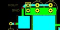
For the switcher and surface mount components, how do you intend making the track contact from non side to comp side.???
Corrected the SS pin link.
E
EDIT: the usual way is a pad on both sides, with a1mm dia hole, solder in a copper wire link thru.
When doing PCB design layout you should have 3 dimensional model in your mind.
Is the SS pin necessary? The datasheet says for normal operations, I can either tie it to Vin or leave it floating. At the moment, i just have it floating.
All the components and traces i have on the layout are placed on the top layer of the PCB. There are no traces on the other side. I plan to put the through hole components in their respective slots and solder them in from under the board.
Am i missing something?

J