hi Johnny,
Downloaded your results image, will look them over, get back to you.
E
EDIT:
Your table of results is incorrect.
Look at my image Red columns .
Note: the Input current will be 'chopped' due to the switching action of the converter, so a regular ammeter will give incorrect results.
Hello Eric,
Ah okay, how would i be able to get the input current? Also, why is my Vout decreasing? I used LTspice to simulate it with a 12Ohms load, the voltage across the resistor is 12V instead of what i got.
That switcher runs at 500 kHz. Any ordinary meter is going to respond to the average. There might be some bobble in the count.
I have some things to do for a bit, but I'll return. I'm actually surprised the circuit works at all. Trying to build a switcher on a plug-in breadboard usually does not end happily. There are large currents at high frequencies with fast edges and a noise-sensitive feedback node. Capacitor characteristics are important. There are several things that can be done to improve your chances. Again, more later.
Hi J,
I read the values in Row 12 of your Table ie: 3.7V with a 12R Load,, are you saying the Vout actually 12V across the 12R load.?
Can you confirm you latest circuit diagram, I appreciate you are 'experimenting' with switcher designs, so the results will not be an optimum design.
E
EDIT:
Added the LTS Power displays. [for my earlier sim]
That should enable you to calc the efficiency at that Vout =3.7 and Rload =12R
Hi eric,
On simulation that i ran with 12Ohms loads, it was getting the same Voltage output as a 100Ohms(12V) whereas my test results doesn't show the same result(3.7V). What could be the reason?
I'm currently using the design you showed in the replies #12.
To measure the input current, do i need to use an oscilloscope? Or is there another way to measure it?
hi j,
Looking at reply post #12 circuit, what are the values of the components R1 and U2.??
Also if U2 is a pot, post an indication of the pots set values, so that I can check with LTS.
OK, let's see if we can improve your chances of success.
Compact careful layout that manages "ground" connections properly and minimizes "loop areas" is very important to getting a switcher to behave.
If current is flowing, there is only one point in any circuit that can be considered to be "zero volts", which I'll call "ground" here so I don't accidentally confuse things by using "common" when referring to something else.
Switchers produce very rapidly changing currents and the current can be large. The paths that the current takes change during the course of a full switching cycle. You can see this by adding current probes to your simulation. Every conductor has inductance. To minimize this inductance it is important to keep "loop areas" as small as possible. Suppose you have to make current flow through a conductor that is 5 cm long. If you form the conductor into a circle, you can see that the magnetic field from any part of the circle isn't going to be able to couple very well to other parts of the circle because of the distance. If you take that conductor and bend it sharply into a hairpin or long narrow "U" shape, you increase the magnetic coupling between the "out bound" part of the wire and the "return" part of the wire. Because the current is flowing in opposite directions in the out and return parts, the magnetic fields cancel and the overall inductance is greatly reduced. The loop are of the circle is large. The loop area of the U is much small for the same length of conductor. The inductance is reduced and the ability of the conductor to couple magnetically to other parts of the circuit is also reduced. Loops of course usually aren't just connections but include components. For example, when the switch in the IC is ON, the input current flows through a loop formed by C1, L1 and U1 and their leads. C1 is there so the loop is at least partly cut off from the external loop of the input power supply and the connecting wires.
The one-point-is-zero problem can be quite a challenge with a switcher, so compromise must be made, but very carefully.
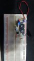
Let's look at your breadboard:
We'll start with some ground cleanup, first on the frequency compensation components. C3, R4 and C5. The parts shape the frequency response of the voltage error amplifier of the IC. It is important to keep unwanted noise and voltage drops out of the connections to these parts. Tighten up the layout of the parts so their leads are as short as possible. It would be better to put them on the same side of the gap in the breadboard as the controller. Make the ground connection for them as short as possible and directly to the ground pin of the controller.
Move R2 so that it very close to the controller, again with its ground end right to the controller.
Instead of using the bus connection at the bottom of the board for ground, use the one at the top, right next to the positive supply.
Trim the leads of C1 and place it close to the IC. This greatly reduces the loop area for the input current.
Trim the leads of C4 and place it close to the diode. This greatly reduces the loop are for the output current.
Connect R1 as close to the output capacitor as possible, rather than close to the diode. This puts the sense point on the right side the unwanted inductance of the connection between the diode and the capacitor.
Move L2 up beside L1 to reduce loop area.
I don't know what you are using for an input supply, but the wires to it should be twisted together to minimize that loop area and unwanted inductance.
When we return ...
we'll consider the aluminum electrolytic capacitors. Based on appearance, C1 might be OK. The others aren't.
hi j,
Looking at reply post #12 circuit, what are the values of the components R1 and U2.??
Also if U2 is a pot, post an indication of the pots set values, so that I can check with LTS.
OK, let's see if we can improve your chances of success.
Compact careful layout that manages "ground" connections properly and minimizes "loop areas" is very important to getting a switcher to behave.
If current is flowing, there is only one point in any circuit that can be considered to be "zero volts", which I'll call "ground" here so I don't accidentally confuse things by using "common" when referring to something else.
Switchers produce very rapidly changing currents and the current can be large. The paths that the current takes change during the course of a full switching cycle. You can see this by adding current probes to your simulation. Every conductor has inductance. To minimize this inductance it is important to keep "loop areas" as small as possible. Suppose you have to make current flow through a conductor that is 5 cm long. If you form the conductor into a circle, you can see that the magnetic field from any part of the circle isn't going to be able to couple very well to other parts of the circle because of the distance. If you take that conductor and bend it sharply into a hairpin or long narrow "U" shape, you increase the magnetic coupling between the "out bound" part of the wire and the "return" part of the wire. Because the current is flowing in opposite directions in the out and return parts, the magnetic fields cancel and the overall inductance is greatly reduced. The loop are of the circle is large. The loop area of the U is much small for the same length of conductor. The inductance is reduced and the ability of the conductor to couple magnetically to other parts of the circuit is also reduced. Loops of course usually aren't just connections but include components. For example, when the switch in the IC is ON, the input current flows through a loop formed by C1, L1 and U1 and their leads. C1 is there so the loop is at least partly cut off from the external loop of the input power supply and the connecting wires.
The one-point-is-zero problem can be quite a challenge with a switcher, so compromise must be made, but very carefully.
Let's look at your breadboard:
We'll start with some ground cleanup, first on the frequency compensation components. C3, R4 and C5. The parts shape the frequency response of the voltage error amplifier of the IC. It is important to keep unwanted noise and voltage drops out of the connections to these parts. Tighten up the layout of the parts so their leads are as short as possible. It would be better to put them on the same side of the gap in the breadboard as the controller. Make the ground connection for them as short as possible and directly to the ground pin of the controller.
Move R2 so that it very close to the controller, again with its ground end right to the controller.
Instead of using the bus connection at the bottom of the board for ground, use the one at the top, right next to the positive supply.
Trim the leads of C1 and place it close to the IC. This greatly reduces the loop area for the input current.
Trim the leads of C4 and place it close to the diode. This greatly reduces the loop are for the output current.
Connect R1 as close to the output capacitor as possible, rather than close to the diode. This puts the sense point on the right side the unwanted inductance of the connection between the diode and the capacitor.
Move L2 up beside L1 to reduce loop area.
I don't know what you are using for an input supply, but the wires to it should be twisted together to minimize that loop area and unwanted inductance.
When we return ...
we'll consider the aluminum electrolytic capacitors. Based on appearance, C1 might be OK. The others aren't.
Wow, thanks for the explanations. I'm currently in the process of sorting out my circuit based on your reply, will update when i'm done. I am using a 9V battery to power the circuit at the moment. I can't wait for part 2, i have read a few papers but fail to understand it completely.
I appreciate and thank you for your time in guiding me. (also @ericgibbs)
John
EDIT: Here's what i've got.The ground wire connecting the pin to ground and the wire for Vin on the IC are both under L1.
I have just tested it with 100R load, the Vout no longer reaches 12V when i tune the 47K pot to 47K connected to the feedback pin. I am now getting Vout of 11V when the pot is set at around 42K ohms. When i increase it(>42K), the Vout drops to 9V. Any reason for that?
Hi John,
A regular 9v dry battery is not the best choice to power SMPS, highish internal internal resistance and quickly falls below the 9V nominal voltage.
Using the USB to power a SMPS could cause problems with any other devices on the USB rails.
I have 'tidied' up your image, the layout looks very good, nice and tight, the Caps look like regular types, not low ESR. ???
I would not draw more than 2-300mA from Vout when using BBoard, the 500kHz frequency of operation on a BB is not a problem.
Will recheck your circuit using 2k and 47k.
Eric
EDIT:
Checked with those values, the Vout is unstable around 1.5V
Could you try a quick test using the values in the second image 18k , 5k6 and a 12R load.
You should get a Vout out of ~5.2v.
Hi Eric,
I'm building this SMPS as a test bench power supply that can be used for other mini-projects.
What would you recommend to use as the power supply?
No the caps are not Low ESR, i will look into ordering some.
I currently do not have the required resistors to test that. Will get back to you asap.
With my current circuit layout, the voltage output can range from 1.28V(when pot is set to 0) to 11V(when pot is set to 42K), anything more than 42K ohms, the voltage output drops to 9V. I don't understand how this happens. Would you perhaps have any clue?
hi,
As you increase the Vout by setting the 47Kpot, if you are using the same load resistor, the load current is increasing.
It is possible that the battery is unable to supply that amount of current, so the Vout will limit at ~9v.
I would re-run test and monitor the 9V battery level.
I would suggest a 9Vdc or 12Vdc wall wart PSU rated at 1 to 2Amps.
E EDIT:
I think you have 47k pot set to 0R when you get Vout =~11v and 44K when its set to ~47k
Not a big deal, just pull it of the BB and rotate it 180 degrees.
I took your advice and replaced the power supply to a 9V wall wart, however only supplying 5V I also rotated the pot but that does not seem to solve the problem. With the wall wart, I was able to get a voltage range from 1.3V at 0K pot , and 14V at ~44K , 9V at 47K. Still the same results.
When i turn the dial on the pot increasing the resistance, it peaks at 14V at 44K Ohms, then drops instantly to 9V when i increase the ohms just by a bit. When i dial it back from >44K, it does not return back to 14V, instead it stays stable at ~8V then drops to 7V and so on. Could it possibly be other components causing this issue?
hi J,
I will look at that problem.
What is the voltage rating of the output capacitor.? Try at least a 25Vwkg.
Be aware that those type of DC connectors come in at least two sizes, ie: 2.1mm and 2.3mm [centre pin dia]
E
hi J,
I will look at that problem.
What is the voltage rating of the output capacitor.? Try at least a 25Vwkg.
Be aware that those type of DC connectors come in at least two sizes, ie: 2.1mm and 2.3mm [centre pin dia]
E
On the output capacitor it says 35V. I found a spare DC connector and wired it up and connected it to the board. I tested the output, I was getting 9.3V across the DC connector.
I ran a test with 1K ohm resistor and my output capacitor blew up.(Now that i think about it, i forgot to consider the polarity of the capacitor) The highest ceramic capacitor i can find has a voltage rating of 16V. http://uk.farnell.com/tdk/ckg57nx7s1c107m500jh/cap-mlcc-x7s-100uf-16v-2220/dp/2210739?st=100uF ceramic
(1) If i were to get this ceramic capacitor, can i solder wires onto it and place it on the breadboard?
(2)Electrolytic capacitors have high ESR, however if i had no choice but to use them, could i put them in parallel to reduce the ESR?
hi,
You should be able to run the Vout upto 14Vdc OK.
You can buy low ESR electrolytics for SMPS.
Connectin caps in parallel does help with the ESR problem.
E
EDIT:
Ran some tests on your circuit with Low ESR caps, slight improvement.
With a 9Vdc supply the max Vout is ~11V
with 5Vdc supply max Vout is ~9V
I would suggest a 12Vdc 1-2Amp wall wart as the voltage supply, if you require a steady Vout of 12Vdc max, adjustable down to ~1.5V
My apologies for not returning with the promised second episode. I will try to do that today.
Good job with fixing the layout! I do now note the polarity of the output cap appears to be wrong.
re #34 - If the input power to a switcher is limited to less than that required to regulate the output voltage the switcher will "collapse" the input supply as it tries to regulate. The duty cycle of the converter will go to the maximum as the switcher attempts to raise the output voltage. The exact effect depends on the nature of the input supply's power limiting - which is actually usually current limiting rather than power and may be "hard" (very precise maximum current, which is typical of a good lab supply), soft" (current starts to limit at some level, but allows current to rise somewhat before reaching the final level) or "foldback" (once the allowable maximum is reached the circuit actually "folds back" the limit to a lower level, and the only way to recover from this is to greatly decrease the load on the supply). With hard limiting, a switcher will often make the output voltage equal to the input voltage. With soft limiting, behavior is less predictable. With foldback limiting all hope is lost - the switcher asks for more and the input supply provides less. Sometimes a switcher go into a perpetual shutdown-retry condition. It this happens at a high enough rate the apparent output voltage measured with a meter may assume some value that seems to make no sense at all. This is where an oscilloscope is invaluable.
hi,
You should be able to run the Vout upto 14Vdc OK.
You can buy low ESR electrolytics for SMPS.
Connectin caps in parallel does help with the ESR problem.
E
EDIT:
Ran some tests on your circuit with Low ESR caps, slight improvement.
With a 9Vdc supply the max Vout is ~11V
with 5Vdc supply max Vout is ~9V
I would suggest a 12Vdc 1-2Amp wall wart as the voltage supply, if you require a steady Vout of 12Vdc max, adjustable down to ~1.5V
Ironically i am powering my circuit using an ac/dc SMPS that can output 12V as well. I will test it out tomorrow and update you when i get my hands on more capacitors.
My apologies for not returning with the promised second episode. I will try to do that today.
Good job with fixing the layout! I do now note the polarity of the output cap appears to be wrong.
re #34 - If the input power to a switcher is limited to less than that required to regulate the output voltage the switcher will "collapse" the input supply as it tries to regulate. The duty cycle of the converter will go to the maximum as the switcher attempts to raise the output voltage. The exact effect depends on the nature of the input supply's power limiting - which is actually usually current limiting rather than power and may be "hard" (very precise maximum current, which is typical of a good lab supply), soft" (current starts to limit at some level, but allows current to rise somewhat before reaching the final level) or "foldback" (once the allowable maximum is reached the circuit actually "folds back" the limit to a lower level, and the only way to recover from this is to greatly decrease the load on the supply). With hard limiting, a switcher will often make the output voltage equal to the input voltage. With soft limiting, behavior is less predictable. With foldback limiting all hope is lost - the switcher asks for more and the input supply provides less. Sometimes a switcher go into a perpetual shutdown-retry condition. It this happens at a high enough rate the apparent output voltage measured with a meter may assume some value that seems to make no sense at all. This is where an oscilloscope is invaluable.
 Facebook
 Google
 GitHub
 Linkedin