Sensor test

Thread Starter

andriasm

Joined Aug 2, 2022
25
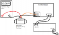
I want to test a sensor that must be powered by a 10 VDC. It is normally connected to the control board which is capable of supplying this voltage with an adequate current. But I need to do a test supplying this voltage outside the control board, because I change the sensor (the sensor that I will test needs more current and with an adjustable voltage source it can deliver more current than the control board). But I need to receive the sensor Vout (its measurement) on the control board.

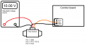
Which of the two attached photos is the correct way to do this test?

Do I need to connect the sensor GND and adjustable voltage source to the control board or do I need to separate them?
 

Attachments

MrChips

Joined Oct 2, 2009
34,807
Drawing #2 is the correct way. The grounds must be conected.

If you are using a variable bench power supply then there is a different answer. Show us a photo or link of the PSU (power supply unit).
 

KeithWalker

Joined Jul 10, 2017
3,607
If the new sensor output is similar to the older one, the second diagram would appear to be correct because the voltage output of the sensor can not be measured using a single wire. There must be a common reference which is the supply negative.
The control board circuitry is probably grounded, so do not ground output from the power supply because it may cause a ground loop and affect the accuracy measurement.
 

Thread Starter

andriasm

Joined Aug 2, 2022
25
If the new sensor output is similar to the older one, the second diagram would appear to be correct because the voltage output of the sensor can not be measured using a single wire. There must be a common reference which is the supply negative.
The control board circuitry is probably grounded, so do not ground output from the power supply because it may cause a ground loop and affect the accuracy measurement.
I didn't understand... You sad me that it must be a common reference between them, but after that sad that to do it can cause a ground loop...
Can you explain again, please?
The control board is suplied by another supply. And it has a ground too. (Like the image attached).
 

Attachments

Thread Starter

andriasm

Joined Aug 2, 2022
25
If you look at the photograph closely you will notice a bridge between -VE output and GND.
This is because the PSU is "floating", i.e. the + and - output is not referenced to GND.
Sorry, my adjustable voltage source is a PS-1500, which don't have a GND. Just - and +. Is there some difference?
 

KeithWalker

Joined Jul 10, 2017
3,607
I didn't understand... You sad me that it must be a common reference between them, but after that sad that to do it can cause a ground loop...
Can you explain again, please?
The control board is suplied by another supply. And it has a ground too. (Like the image attached).
I hope this explains the difference:
Ground Loop.jpg
 

DickCappels

Joined Aug 21, 2008
10,661
The output of your flow sensor need to have a way to return current back to the sensor. That is why you should connect the sensor's ground to the control board. If it were radio you would not need to connect the ground but it is not radio.
 
Top