Seeking ideas for buggy ground speed governor

Thread Starter

strantor

Joined Oct 3, 2010
6,782
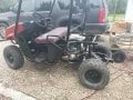
I have a gas-powered UTV (utility "golf cart") that I've modified to be quite fast. After I get the brakes and suspension up to the task, I intend to further modify it to be able to reach highway speeds. For no good reason (just because I want to), I am slowly turning it into something more like a car. I'll be putting a PLC in the buggy with a touchscreen HMI in the dashboard. This will allow me to have an infinitely configurable dashboard so that I don't have to drill a bunch of holes in the dash to mount gauges and switches, and then be forever unsatisfied with the way I laid everything out.

I would like to have a way to slow it down, in 2 or more steps, so that my kids can enjoy using it without me having to worry about them being involved in a 50mph rollover. I envision a login screen where, depending on the password you enter, one or another profile is loaded, and max speed is a part of the profile. If my 8 y/o logs in, her speed will be limited to 10mph or so. For my 13 y/o, maybe 20. For me, none.


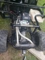
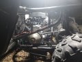
So I'm after some means of an adjustable ground speed governor. This buggy employs a CVT (Continuously Variable Transmission), which I don't fully understand the operation of, but I think that engine RPM is not always directly correlated to vehicle ground speed. Therefore the governor will need to be a closed loop with wheel RPM as feedback. I have tossed around many ideas about how to do it, and can't settle on one. I feel like there is a better solution I'm not thinking of. Thought I would bounce it off you fine folk.

Here are my ideas so far:
  1. When max speed reached, Cut spark to spark plugs. Simplest solution but this won't stop fuel being dumped into the cylinders, and could result in something nasty.
  2. Complete drive-by-wire. Potentiometer on accelerator pedal, servo on throttle lever at engine. This offers the highest level of control with the easiest implementation, but also introduces the most opportunity for catastrophic failure. Any number of failure modes could result in runaway operation. Not willing to take the risk.
  3. A servo linked by spring to the throttle lever on the engine, in opposition to the accelerator pedal cable (also linked to throttle lever by spring). A PID loop monitors speed, and as max speed is approaching, begins a game of tug-of-war with the operator's foot. The result would hopefully be a gradual settling in at max speed, no abrupt drop-off, and the only failure modes would still leave the operator in control (able to achieve max speed or able to achieve zero speed, but no runaway operation).
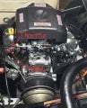
  4. Replace the carburetor and magneto with fuel injection and electronic ignition. This would be cool, and offer a great level of control, but it's a bit more advanced than I would like to go for now, or maybe ever.
  5. An array of solenoids with springs connected in opposition to the accelerator pedal, same concept as option #3, but one spring & solenoid for each speed profile. Depending on individual spring tension, the engine throttle lever only moves at some ratio of accelerator pedal travel.

I am leaning towards option #3, but it doesn't feel as elegant of a solution as it could be. Surely there is a better idea? What say you?
 

ci139

Joined Jul 11, 2016
1,898
? hydraulic piston that provides "additional" support to your foot weight at a high speed -- it's a joke but a possible option
 

Alec_t

Joined Sep 17, 2013
14,280
How about mechanical stops to limit throttle pedal movement? Each driver profile has a respective mechanical key to unlock/lock the appropriate stop.
I envision a login screen where, depending on the password you enter, one or another profile is loaded
Your 8 y.o will soon crack the passwords ..... and you'll forget them :).
 

geekoftheweek

Joined Oct 6, 2013
1,201
How about a picture of the engine and such. I've only been in a couple golf carts, but the CVT part works pretty much the same as many other toys if I'm thinking right.

Cutting the spark will probably eventually end up with a nice back fire that blows the exhaust apart. All it will take is enough down hill runs to make it happen. If your kids are like I was back then they'll figure it out and have a blast getting it to happen until it finally lets loose then have no idea how it happened.

Most small engines have a spring that pulls against the governor to make the carb open up. That would probably be a good spot to work your magic along with some pressure at the right point on the belt if it's what I'm thinking.
 

geekoftheweek

Joined Oct 6, 2013
1,201
I can't say for certain, but the first couple minutes of this is how I envision your CVT to work.
Although the engine speed won't exactly regulate ground speed (there is a little gray area), it will be predictable.
 

geekoftheweek

Joined Oct 6, 2013
1,201
What exactly are you working with?

I had another thought. Back in the 70's (I believe) John Deere came out with a vari-speed lever on their lawn tractors. What it was simply is two pulleys built into one. It looked like two pulleys stacked, but the center sheave slid side to side. The lever was sort of like a second clutch pedal that would keep the belt between the engine and pulley a little loose so it wouldn't be able to travel down, force the sheave over, and bring the belt between the pulley and transmission to the top. I think the concept it used by many inexpensive mowers today.
 

crutschow

Joined Mar 14, 2008
34,281
The simple, small-engine, automatic CVTs I have seen (starting with an old Cushman motor scooter in the 50's) have a large, wide V-belt that goes between two large pulleys, with the one on the engine allowing the two pulley sheeves to change spacing (similar to what geek mentioned).
The spacing was controlled by centrifugal weights, so it started out with maximum spacing, putting the belt at the bottom of the pulley for maximum torque (1st gear).
Then as the speed increased, the rotating weights started pushed the pulley sheaves together, causing the belt to slowly ride up, reducing the gear ratio, (going to a continuously higher gear).
The belt tension was maintained by a spring with the fixed pulley being on a pivot, to keep the belt tight independent of the pulley spacing.

The Cushman had the usual, somewhat disconcerting operation of a CVT, in that if you opened the throttle fully, the engine would jump to a fairly high speed, but would tend to drone on at a near constant RPM as the ground speed increased.
 

Thread Starter

strantor

Joined Oct 3, 2010
6,782
I can't say for certain, but the first couple minutes of this is how I envision your CVT to work.
Although the engine speed won't exactly regulate ground speed (there is a little gray area), it will be predictable.
Yes, that's the type of CVT in question.

The simple, small-engine, automatic CVTs I have seen (starting with an old Cushman motor scooter in the 50's) have a large, wide V-belt that goes between two large pulleys, with the one on the engine allowing the two pulley sheeves to change spacing (similar to what geek mentioned).
The spacing was controlled by centrifugal weights, so it started out with maximum spacing, putting the belt at the bottom of the pulley for maximum torque (1st gear).
Then as the speed increased, the rotating weights started pushed the pulley sheaves together, causing the belt to slowly ride up, reducing the gear ratio, (going to a continuously higher gear).
The belt tension was maintained by a spring with the fixed pulley being on a pivot, to keep the belt tight independent of the pulley spacing.

The Cushman had the usual, somewhat disconcerting operation of a CVT, in that if you opened the throttle fully, the engine would jump to a fairly high speed, but would tend to drone on at a near constant RPM as the ground speed increased.
Yes, there is some incongruity between engine speed and ground speed. I don't have a tachometer on it yet, but putting around in the yard at 10mph sometimes the engine sounds as if it's running the same RPM as when I'm going max speed. This is why I don't think a simple throttle limit would work. I think it needs to be a closed loop, monitoring ground speed.

Some Gas powered golf carts with this kind of CVT have a mechanical ground speed governor that is a function of the rear transaxle. It works the same way as a mechanical engine governor; a weighted gear is spun, and the faster it spins, the harder a lever is pressed, and that lever works in opposition to the throttle lever.

I don't have such a transaxle with mechanical governor, and even if I did, it would only work for whatever speed it was designed to work. I would like to replicate the results with electronics, and in doing so also open up the ability to set arbitrary governor limits.
 

Thread Starter

strantor

Joined Oct 3, 2010
6,782
What exactly are you working with?
It is an American Sportworks Bulldog UTV.
CVTech Series 06 drive pulley
CVTech Invance driven pulley
Dana/Schafer 265 transaxle
Originally powered by a 9.5hp Kohler engine, now powered by a 670cc Predator V-twin engine.

Partially disassembled in pictures, but they were the pictures where you can sort of see the drivetrain.
 

Attachments

Last edited:

crutschow

Joined Mar 14, 2008
34,281
This is why I don't think a simple throttle limit would work. I think it needs to be a closed loop, monitoring ground speed.
Yes, all cruise controls monitor ground speed, as the engine speed vs. ground speed depends upon the gear you are in, of course.
To do that, you can mount one or more small magnet(s) on the right pulley in the right picture with a magnetic pickup sensor to generate pulses proportional to the ground speed.

How to use that signal to control the speed is another problem, of course.
A linear actuator might work.
Attach a spring from that to pull the throttle closed, and a spring from the accelerator to pull the throttle open.
It's fail-save since releasing the throttle will always close it, no matter the position of the actuator.
 

cmartinez

Joined Jan 17, 2007
8,218
Question. And please forgive me in advance if I wasn't paying close attention to what you've just described. How does the cart's throttle pedal govern the engine? Is it mechanically connected to its air or fuel intake? Or is it of the anti-parallel pot type that goes into a computer?
 

Thread Starter

strantor

Joined Oct 3, 2010
6,782
Yes, all cruise controls monitor ground speed, as the engine speed vs. ground speed depends upon the gear you are in, of course.
To do that, you can mount one or more small magnet(s) on the right pulley in the right picture with a magnetic pickup sensor to generate pulses proportional to the ground speed.

How to use that signal to control the speed is another problem, of course.
A linear actuator might work.
Attach a spring from that to pull the throttle closed, and a spring from the accelerator to pull the throttle open.
It's fail-save since releasing the throttle will always close it, no matter the position of the actuator.
Do you describe something like option #3, but operating in reverse (fail-safe) fashion? Instead of the servo fighting against the operator, it fights with the operator, against a fixed/static spring (only to the extent required to be able to reach setpoint max speed)?
 

Thread Starter

strantor

Joined Oct 3, 2010
6,782
Question. And please forgive me in advance if I wasn't paying close attention to what you've just described. How does the cart's throttle pedal govern the engine? Is it mechanically connected to its air or fuel intake? Or is it of the anti-parallel pot type that goes into a computer?
No computers at all currently. All mechanical.
 

Attachments

geekoftheweek

Joined Oct 6, 2013
1,201
@strantor thanks for the pictures and the details!!

I think you are right about engine rpm and cruising speed. My couple times on a golf cart where short trips over rough terrain, and my snowmobile experiences were always full throttle except long enough to hit the brake, plant a ski, and shift my weight to toss the back whatever direction I needed to go. I was always borrowing the old 70's and 80's units off friends while they had the late models that were like driving a Cadillac compared to keeping a wheelbarrow upright.

Anyways...
It's kind of like there's a point where the springs and weights almost balance themselves and as long as the engine is providing a little power to keep it at speed everything settles where it is. The second your driven pulley becomes the drive pulley everything starts moving back to "home" position or wherever it needs to be at that point.

I took a picture of the 301 cc Predator I have to show what I was thinking. I looked through the manual for yours, but couldn't find a drawing of what I was after to describe where my thoughts were going.

predator-governor.jpg

The spring in the upper right comes from the throttle lever. The governor lever in the center is connected on the left to the carburetor butterfly by a solid rod. Since the governor turns the post clockwise to move the carb butterfly I was thinking make some sort of servo driven lever that would contact the governor lever and push it clockwise. The governor would still work as it should (when needed), If you have a failure of some sort it wouldn't hold the throttle open, but rather make it so it wouldn't rev up like it should or you would be left with the standard mechanical governor depending on how it fails. It's probably located under the air box on yours which would make it a little more tamper resistant (they'll figure it out someday).

I was also thinking a rubber wheel of some sort to force the drive pulley open by way of either pushing the belt back towards the middle, or (even better) a wheel that actually rides a little above the belt and forces the drive clutch open. Maybe since the outside of the driven pulley is what moves on that end you could attach some sort of sensing device that can read it's position along with your other ground speed sensor and between the two work out how you want the engine to react.

It's possible that with enough experimentation you may be able to simply regulate the rpm to make the belt move where you want it also.

This sounds like a challenge, but a fun one and I wish you good luck on this!!
 

geekoftheweek

Joined Oct 6, 2013
1,201
I started to think maybe the way to go would be:
Monitor engine RPM.
Monitor driven pulley position.
If driven pulley is past it's limit have the servo push the governor arm to lower RPM enough to take the drive out of the drive pulley and let the driven pulley close up a little.
If the pulley or road speed is not at the programmed limit the servo would retract and let the carb / governor do it's normal routine.
Road speed would make a good redundant feature, but even though sped and pulley position will always have the same relationship in the end it just seems the pulley position would react smoother and be more accurate in my mind.
 

geekoftheweek

Joined Oct 6, 2013
1,201
One last thought for the day... Public go kart tracks have some form of radio controlled governors on their units to make you slow down at the end of the race, or limit speed for different age groups, number of racers, or whatever the case may be. I didn't look around to find out anything, but maybe look into that for inspiration also.
 

geekoftheweek

Joined Oct 6, 2013
1,201
I just went back and actually read what everyone else has said lately instead of skimming for details. It seems my thoughts were pretty much already covered and I don't mean to insult your mechanical knowings with the picture and details... just sometimes helps to be able to show and explain rather than explain.
 

crutschow

Joined Mar 14, 2008
34,281
Do you describe something like option #3, but operating in reverse (fail-safe) fashion? Instead of the servo fighting against the operator, it fights with the operator, against a fixed/static spring (only to the extent required to be able to reach setpoint max speed)?
No, I was thinking the same as option #3.
Both the operator and the servo are connected in opposing directions to the throttle with springs, but the springs are adjusted such that the throttle will always go back to the idle position if the accelerator is not pressed, regardless of the position of the servo.
Offhand I can't think of a better way, if you want it to be failsafe.
 

geekoftheweek

Joined Oct 6, 2013
1,201
Just had some inspiration from a tractor out in the shed... hydraulic.jpg

This is the hydraulic mower deck (or whatever is attached) lift for my old Cub tractor. How it works is you set your position with the lever that in turn moves the bottom of the left hand linkage.

Say you move the lever left, the linkage at the bottom would move right which would in turn push in on the valve casing the cylinder to extend. As the cylinder extends the linkage would then pivot at the bottom causing the valve to center, and you would be at your desired height.

Edit... I did have the cylinder retracting until I realized that would be a runaway type situation.

Instead of cylinder would be an actuator of some variety, the lever would translate to your gas pedal, and the valve portion would be the throttle cable going to the engine.
 
Last edited:

cmartinez

Joined Jan 17, 2007
8,218
Another question ... is the fuel pump electric or mechanical?

And here's a small proposition: Install a couple of solenoids that will stop the throttle at preset positions when they're inactive. Activating them would remove said stops and allow the driver to get full performance out of the cart.
 
Top