Seeking for a zerocrossing SSR without using Microcontroller

Thread Starter

Hasan2019

Joined Sep 5, 2019
64
Hi There,
Hope this post find you well.
May be or may not you would love it, because this issue has reached huge number of problems. Someone could say "school project for infants".


I was trying to build a SOLID STATE RELAY with zero crossing switching. Similar to this type http://demo5.zmpress.net/solid-state...ys-xssr-2402p2

In my case I was using MOC3021 [url=http://www.farnell.com/datasheets/97984.pdf]www.farnell.com/datasheets/97984.pdf[/url]
and BTA100-800A.
dv/dt of BTA100 is 500V/us.
My application is 380V 40A load switching. Lets say for inductive and capacitive load.

Main issue is "someone said me not to use any microcontroller to drive the TRIAC gate".
So, random switch type SSR has been chosen, similar to this one
io27.gifIt might be non-zero crossing type SSR. 5V dc as been used that does not make sense for gate switching or its keeping the gate ON always.
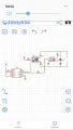
How about using a TIMER as follows?
555_based_zcs_triac.PNG

Can we control zero crossing with this idea?
I think I need a zero crossing detecting circuit, what do you think? Does it possible to use this circuit for zero current/ voltage crossing?
 

Attachments

Last edited:

Thread Starter

Hasan2019

Joined Sep 5, 2019
64
hi,
Using a MOC ZCD type, say a MOC3081, would be the simplest solution.
E
Which kind of circuit you want me to use? I need to prove that ZC works. If its random type meaning that, only 5~9V dc with a current limiting resistor added to the head of MOC would not proven for ZC! For ZC detecting circuit, did you see Microcontroller is used! That has been sensed later, take a lookxCIWd.png
 

ericgibbs

Joined Jan 29, 2010
18,841
hi H,
It depends on what type of current control you require thru the load.
If you are only using 'burst' control, ie: the Triac either On or Off, with On occurring at the ZCD point on the mains cycle, I would use a ZCD MOC.
If you require more precise control over the load current, add a Opto ZCD detect circuit together with a MCU, in that way you can control the firing angle of the Triac [ knowing the ZCD point]

Which mode of load current do you want , Burst or Proportional Control.??

E
 

Dodgydave

Joined Jun 22, 2012
11,301
Timed firing is ok for ordinary light dimming manually, where the triac gate is triggered a delay after Zero crossing, on both cycles, when using a Micro, it needs to know when the mains is at zero in order to apply the gate trigger at some delay after zero, otherwise it's just firing random pulses and it won't work.

Your Zcd optocoupler only works on Half cycles, ideally you want a bridge rectifier for the U2 optocoupler , and use a MOC3063 for U1.
 

Thread Starter

Hasan2019

Joined Sep 5, 2019
64
You have nicely caught the point what I have wanted to know. Thanks a lot. Looking at the application note AN-3004, AC signal should be synchronized with firing angle and pulse widths.

Dimmer type may not achieves ZCD. Not sure which kind of control I should choose, but my load will be capacitive type. If you look at my first typical link, jp/cn company has made a module.

It has recomended by a SSR company that, dimmer/ random type is suitable for inductive load because I and V has phase angle for Pf< 1. My application is for 40A capacitive load, but initially I am resting with 2A 220V inductive load.

I have read the physics behind using " snubber" and transient issues. MOC 3021 datasheet suggest how to use resistive and capacitive load.

Dont you mean without MCU, exact ZCD point cant be visible? My customer said, even its not touched the ZCD point it will be no problem!

Am I wrong with using NE555? The trimmer is just altering the pulse width, isn't it? Or its just same like using DC sourse since MOC 3021 doing the ZCD job!

Do you have any idea with using TTL for such ZCD ?
 

Dodgydave

Joined Jun 22, 2012
11,301
The 555 is just firing random pulses , so the result will be erratic and not work , the simplest method for zcd is the opto and bridge rectifier like U2, this will give a pulse out any every Zero crossing (10mS for 50Hz, 16mS for 60Hz)
 

Thread Starter

Hasan2019

Joined Sep 5, 2019
64
The 555 is just firing random pulses , so the result will be erratic and not work , the simplest method for zcd is the opto and bridge rectifier like U2, this will give a pulse out any every Zero crossing (10mS for 50Hz, 16mS for 60Hz)
Great! This time what kind of circuit you would suggest? Does it independent from MCU?
Don't you mean MOC will generate 10~16mS pulse ? What wouldbe the benefits for MOC3081 instead of MOC3021? Depending on dv/dt of TRIAC BTA100 which one is better fit?
How could you generate pulse then?
Take a look this circuit that may be what you are trying to figure outZero-Crossing-Detector-Circuit-ZCDC.png
 

Attachments

Last edited:

Dodgydave

Joined Jun 22, 2012
11,301
Great! This time what kind of circuit you would suggest? Does it independent from MCU?
Don't you mean MOC will generate 10~16mS pulse ? What wouldbe the benefits for MOC3081 instead of MOC3021? Depending on dv/dt of TRIAC BTA100 which one is better fit?
How could you generate pulse then?
Take a look this circuit that may be what you are trying to figure outView attachment 193467
Yes thats right, full wave bridge will get both sides of zero volts, so you will get a pulse at Zero every half cycle of mains.
 

MaxHeadRoom

Joined Jul 18, 2013
28,681
I was trying to build a SOLID STATE RELAY with zero crossing switching. Similar to this type http://demo5.zmpress.net/solid-state...ys-xssr-2402p2

In my case I was using MOC3021

Can we control zero crossing with this idea?
I think I need a zero crossing detecting circuit, what do you think? Does it possible to use this circuit for zero current/ voltage crossing?
MOC3021 is Not zero crossing but random phase.
See Fairchild AN-3006, AN-3003.
Zero cross is MOC316X, MOC308X
Max.
 

Thread Starter

Hasan2019

Joined Sep 5, 2019
64
Yes thats right, full wave bridge will get both sides of zero volts, so you will get a pulse at Zero every half cycle of mains.
Thank you once again.
Now do you want me to connect this circuit to MOC3081 along with snaubber, load ?
MOC3081, it self is not ZCD? Does output of 4N25 is enough to connect with BTA100-800A?
 

Thread Starter

Hasan2019

Joined Sep 5, 2019
64
hi H,
It depends on what type of current control you require thru the load.
If you are only using 'burst' control, ie: the Triac either On or Off, with On occurring at the ZCD point on the mains cycle, I would use a ZCD MOC.
If you require more precise control over the load current, add a Opto ZCD detect circuit together with a MCU, in that way you can control the firing angle of the Triac [ knowing the ZCD point]

Which mode of load current do you want , Burst or Proportional Control.??

E
Your response is pretty much concerns with this project. To see the ZCD and firing angle we must need a MCU meaning that derecting circuit that I posted with U2 4N25 is must.
 

Thread Starter

Hasan2019

Joined Sep 5, 2019
64
MOC3021 is Not zero crossing but random phase.
See Fairchild AN-3006, AN-3003.
Zero cross is MOC316X, MOC308X
Max.
At least need to find out a theoretical clue that MOC 3081 is zerocrossing. What makes it different from MOC3021, what makes MOC3021 to be random phase in character!
 

be80be

Joined Jul 5, 2008
2,072
The MOC3021 does not have zerocrossing The MOC3041 has the same rating of the 3021 but it has zerocrossing
so does the MOC3081
The MOC3081 is 800 volt peak the 3041 is 400 volt peak they both have zero crossing circuit built in.
 

MaxHeadRoom

Joined Jul 18, 2013
28,681
With the zero cross MOC316X & MOC308X series, when current through the LED occurs, the detector of the zero crossing opto coupler switches to the conducting state only when the applied AC passes through zero or close to it.
Max.
 

Thread Starter

Hasan2019

Joined Sep 5, 2019
64
With the zero cross MOC316X & MOC308X series, when current through the LED occurs, the detector of the zero crossing opto coupler switches to the conducting state only when the applied AC passes through zero or close to it.
Max.
Don't you mean pin4 of MOC3081? If its detecting point then whats your basic idea to see it in Oscilloscope? Isn't it mounted with internal circuitry that has been isolated from anode and cathod of LED. If you look deeply its part symbol its nothing but a TRIAC in output!
 

Thread Starter

Hasan2019

Joined Sep 5, 2019
64
moc_3081.PNG

MOC3081 datasheet tells us to calculating snubber circuit. Damping, Transisent, Resonance all are considerable.
But for 380Vpk, 40 A, PF=-0.9 capacitive load, what would be wattage of resistor 360R,39R,340 R?
Maximum 3W?
My pcb need more space ?
 
Top