 Facebook
 Google
 GitHub
 Linkedin
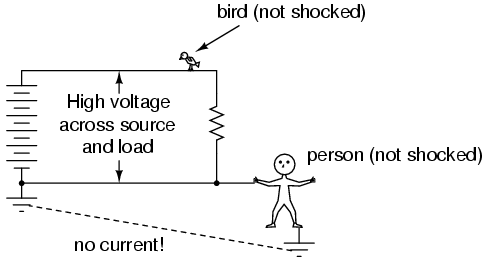
There was some explanation about common points of a wire in another section. That taking a voltage reading at two points on the same wire will result in no voltage difference.
So in this case where the person is grounded along the same wire as a ground, they are common to each other which prevents him from being shocked; no voltage difference.
But he is in parallel to the wire so I imagine the only real reason he's not getting shocked is because the ground isn't going to be as good a conductor in this scenario as the wire of the circuit.
But now let's replace this person and ground with a thicker wire. Even though this thicker gauge wire is connected in common to the original wire at two points, current will travel across this thicker(less resistant) wire rather than the original.
So common testing is for determining whether you're on the same wire. You'll get no voltage difference. But after a load, there will be a voltage drop. That begins a second wire and a difference in potential.
This part is fuzzy, why does a difference in potential exist now in this second wire after the load even though it's in series with the original wire. I don't understand what this drop actually is that allows us to measure this difference at this point of the circuit(just after the load) as opposed to on the original wire. Does the load act as a blocker between wire 1 and wire 2? Because if we short circuit the source with 1 wire we get a difference in potential. But now wire 1 added to the circuit with load and wire 2, we lose that difference in potential on wire 1 but why?
::"image removed due to hosts image bandwidth constraints"
Last edited:


