Scope Telequipment D61A;horizontal position fault

Re your questions in post #192:

- I have been checking on the tube and discovered that -Vg1 is 21V; in the tube description the range mentioned is 75-35 V. I measured relative to the cathode. Think EMF NOT OK.
The beam cut off range is (-75) through (-35) volts per kilovolt applied to anode #1 (a1) --- Whereas the absolute maximum applied voltage range is (-200V) through (-1V) --- hence your reading (-21V) is not inconsistent with proper operation!:)

- In tube description I read : pda spiral resistance: whats that?
The Post Deflection Acceleration 'electrode' (a4) is implemented as a graphite spiral 'printed' on the envelope of the tube -- (The referanced specification indicates that the resistance of said spiral = 75MΩ)

- I also read on p 4 of tube description you provided: Vs (pattern correction Voltage):What is that and where can I measure that?
Geometry correction is achieved via 'bias' on 's' (Pin 9) -- Note, however, that the presenting symptoms are not consistent with difficulty in this area!:)

- I measured over R309 (2.2K): 187V
over R306 and R308: O V (guess R306 NOT OK; 308 OK)
Inasmuch as the appropriacy of the above cited readings is contingent upon many conditions (i.e. control positions, modes, etc..) we'll leave them in abeyance for the nonce --That said, we'll revisit them should they 'lie in the path' of the troubleshooting process...:cool:

Very best regards
HP:)
 
Last edited:
Alright -- first of all let's investigate the anomalous interaction of horizontal position and intensity:

-Observe EMF across R69 while varying R301 over its range
Please post E(R69) for CCW, Mid and CW positions of R301

-Observe EMF at test point 156/12 (Figure 5) while varying R301 over its range
Please post E(test point 156/12) for CCW, Mid, and CW positions of R301

Best regards
HP:)
 
Thanks for all info Hypatia. I'll be away for a few weeks and at my return i'll check the points you mentioned above;In the mean time, have some nice weeks!;):)
You too! -- And please rest assured we will get it working!:cool: -- I haven't been 'beaten up' by an O'scope yet!:)

Have a pleasant vacation!:):):)

Best regards
HP:cool:
 

Thread Starter

patpin

Joined Sep 15, 2012
405
Alright -- first of all let's investigate the anomalous interaction of horizontal position and intensity:

-Observe EMF across R69 while varying R301 over its range
Please post E(R69) for CCW, Mid and CW positions of R301

-Observe EMF at test point 156/12 (Figure 5) while varying R301 over its range
Please post E(test point 156/12) for CCW, Mid, and CW positions of R301

Best regards
HP:)
Hallo Hypatia; all OK?
On the first test: On R69 (at slider) and R69 in MID position::
R301: CCW/MID AND CW -0,92 (no change with R301):
(turning R69 itself the slider goes from-12,18V ( in CCW) to 0 V (in CW) )

The second test: at 156/12:
R301 CCW: 118.9
R301 MID: 118.9
R301 CW: 118.7
 

Thread Starter

patpin

Joined Sep 15, 2012
405
Since I find the --12,18V a bit high (should be -13V) and I do not have the fenomenon of the fulll visibility of the baseline at warming up anymore, I remeasured tensions
WALL: 232V AC ;
AC at TRAFO;
expected and measured V
234; 233
214;213
117;114
107;104
100;92
13; 12
13;12

TRAFO temperature feels normal; at ELCO's also;
 
@patpin -- Nice to see you back on the fora!:)

I apologize that, between the exigencies of 'real life' and prior commitment to @Aleph(0) 's EHT thread, I may be 'scarce' for the next week or so... In the meantime, please keep an eye on this thread as I will post observations/questions/suggestions as time permits (Moreover, assistance from other members may be forthcoming!:cool:) --- I expect to be in a position to offer you my (well-neigh) 'undivided attention' beginning on or about the week of March 7:):):)

Thanks for the readings! -- I will analyze same and try to post conclusions/ 'next steps' sometime tomorrow:cool:

Very best regards
HP:)
 

Thread Starter

patpin

Joined Sep 15, 2012
405
@patpin -- Nice to see you back on the fora!:)

I apologize that, between the exigencies of 'real life' and prior commitment to @Aleph(0) 's EHT thread, I may be 'scarce' for the next week or so... In the meantime, please keep an eye on this thread as I will post observations/questions/suggestions as time permits (Moreover, assistance from other members may be forthcoming!:cool:) --- I expect to be in a position to offer you my (well-neigh) 'undivided attention' beginning on or about the week of March 7:):):)

Thanks for the readings! -- I will analyze same and try to post conclusions/ 'next steps' sometime tomorrow:cool:

Very best regards
HP:)
Thanks Hypatia; no hurry. In the mean time I bought a bitcope BS05. Probably it will help to debug on the antique scope... but i'll have to learn it first. o_O
 

Thread Starter

patpin

Joined Sep 15, 2012
405
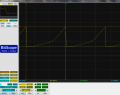
Did a test with bitscope with Time/div on 10 µS on testpoint 156/G and get: pulse with 41,6V peak to peak an duration of 130µS
upload_2016-2-26_0-0-2.png
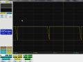
When I do the same on point 156/F I get the reverse pulse (as in the manual) but with peak to peak 16V;
 
Did a test with bitscope with Time/div on 10 µS on testpoint 156/G and get: pulse with 41,6V peak to peak an duration of 130µS
View attachment 101348
When I do the same on point 156/F I get the reverse pulse (as in the manual) but with peak to peak 16V;
While I haven't had time to study your results yet, I felt I must advise you to please exercise extreme caution while 'prodding about' with your digital scope! Case in point; the deflection plates (of the instrument under test) are near acceleration potential (with respect to the cathode) -- Please, always make doubly certain that maximum P-P EMFs aparent under a proposed test condition cannot exceed your digital scope's maximum input rating under the worst-case fault scenario! Moreover, please be wary of 'shorting out' the test circuit via the test scope's return lead! -- Digital instruments seldom grant second chances!:eek::(

I promise to have a good look at your results ASAP!:):):)

Best regards
HP:cool:
 
Last edited:

Thread Starter

patpin

Joined Sep 15, 2012
405
While I haven't had time to study your results yet, I felt I must advise you to please exercise extreme caution while 'prodding about' with your digital scope! Case in point; the deflection plates (of the instrument under test) are near acceleration potential (with respect to the cathode) -- Please, always make doubly certain that maximum P-P EMFs aparent under a proposed test condition cannot exceed your digital scope's maximum input rating under the worst-case fault scenario! Moreover, please be wary of 'shorting out' the test circuit via the test scope's return lead! -- Digital instruments seldom grant second chances!:eek::(

I promise to have a good look at your results ASAP!:):):)

Best regards
HP:cool:
 

Thread Starter

patpin

Joined Sep 15, 2012
405
Other measurment on 156/F: peak to peak about 4V; medium level 104V; NOT OK; exchanging TR33 for TR37 and viceversa: no effect;
upload_2016-2-26_12-11-14.png
 
Last edited:
I am taking care of protecting the bitscope by measuring with DVM on DC and AC before connecting:rolleyes: and even then always use 10:1 probe first.
Kudos!:cool: --- I apologize should my post have seemed a tad condescending!:( --- It's merely that I've seen too many cases of test equipment damage owed to negligent application of same -- Clearly, you know what's to be appreciated in the ways of caution!:):):)


C44 fast since it is PS : It is a short
--Emphasis added--
Sounds promising!:cool::cool::cool:

t's a 1.5 nF "PS"..Can I replace it with a ceramic
Polystyrene (dielectric) Caps exhibit a high degree of stability/predictability over temperature -- hence my strong recommendation that replacement is with another Cap of the same type! --- That said, if there will be a delay in acquisition of a proper replacement - you may certainly temporally substitute it with an appropriately specified ceramic type (to determine the extent to which the difficulty has been isolated):cool::cool::cool:

Good luck!
HP:)
 
Last edited:

Thread Starter

patpin

Joined Sep 15, 2012
405
Kudos!:cool: --- I apologize should my post have seemed a tad condescending!:( --- It's merely that I've seen too many cases of test equipment damage owed to negligent application of same -- Clearly, you know what's to be appreciated in the ways of caution!:):):)


--Emphasis added--
Sounds promising!:cool::cool::cool:


Polystyrene (dielectric) Caps exhibit a high degree of stability/predictability over temperature -- hence my strong recommendation that replacement is with another Cap of the same type! --- That said, if there will be a delay in acquisition of a proper replacement - you may certainly temporally substitute it with an appropriately specified ceramic type (to determine the extent to which the difficulty has been isolated):cool::cool::cool:

Good luck!
HP:)
Ok i'll look for a ceramic one first.
Hope I didnt destroyed it by desoldering...


Hello, Where can one find such PS caps? Dont find them at the current stores overhere.
Hello, Where can one find such PS caps?
 
Top