schematic help needed

Thread Starter

minkey01

Joined Jul 23, 2014
185
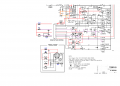
1) could someone read this schematic and tell me how many volts are going through each of the highlighted buttons?

or circle which points in the circuit jpg that i could use a multimeter to read the volts.

-----------

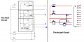
2) also, i can get an amp reading just by putting my multimeter in series with the buttons, correct?

thank you for the help.
 

Attachments

MrCarlos

Joined Jan 2, 2010
400
Hello minkey01 -Nice to read you again.

The voltages on the buttons circled in yellow is about 11 V.
Follow the small arrows starting where it says: Start Here.
That's just an example of how flows the voltage signal to energize the relay K1, called operation.

Of course You can measure the current flowing through the buttons connecting the multimeter in series with them.

Why did not continue over here ?:
switch expert mod help needed
http://forum.allaboutcircuits.com/showthread.php?p=753744#post753744


Attachments

Thread Starter

minkey01

Joined Jul 23, 2014
185
Thank you, MrCarlos!

What would be a good solid-state relay or regular relay to replace these momentary buttons?

control signal : 3-15V ~200 µA
controlled signal : ~11V from your post


Any component part number ideas?

Thank you!!
 

MrCarlos

Joined Jan 2, 2010
400
Hello minkey01

I think you could use the same relay that internally has the stereo tape deck, which uploaded the diagram.
It is very likely that one side has its part number.

You could also look into eBay. asks relays for 12 Volts ..


MrCarlos

Joined Jan 2, 2010
400
Hello minkey01

But what you will use the device listed in the link you enclose ?

As you mention in your other topic, I understand that you intend to change the control mode for stereo tape deck.
Do it like you do, you'd have to press any button to activate the operation that you want to do it the Stereo Tape Deck. Or close a switch or connecting two wires, Etc.

Let's go back to what you mentioned over there:
http://forum.allaboutcircuits.com/showthread.php?p=752450#post752450
I would like to modify it to this : No FF. No REV functions. No buttons. Only 2 jack inputs. If I send in a control voltage into jack 1 it will play. If the voltage into jack 1 is 0 it will stop. If I send in a control voltage into jack 2 it will record. If the voltage into jack 2 is 0 it will stop the record.

Therefore, all you want to do the new control is:
Play / Stop
Rec / No Rec


Currently control works: (You said it).
Now to record you must hit REC and PAUSE at the same time, then they light up.
When you are ready to record you then hit PLAY and it starts to record.

One idea that might work is that you can see in the attached image.
Three relays are needed to achieve the goal.
2 SPDT K1 and K2.
1 DPDT K3.
And 3 diodes 1N4005.

I hope you serve that circuit.
 

Attachments

Top