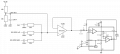
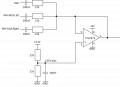
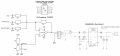
Schematic for a 3 channel analog audio mixer

Thread Starter

freeflyer

Joined Sep 9, 2016
169
? is your chip authentic ? is it operational (hasn't not overheated)
Which chip ? The TLV2372 is authentic, I bought it from RS and have tried several of them. I have no idea bout the LM4871 dev board, that was from ebay. I do have some LM4871 from RS, so could try replacing the one on the dev board
 

Thread Starter

freeflyer

Joined Sep 9, 2016
169
hi ff,
The TLV has no gain, just a buffer???
E
Hi, thats correct. The individual channels do not need any gain when used with the PAM8302A, I am just trying to mix all 3 channels into a single mono channel. I originally did the mixing passively (resistors and capacitors) but this attenuated the signal slightly, so I thought adding a unity gain buffer would help prevent this. Should I add gain to the TLV and if so how do I know what gain it should be ?
 

ericgibbs

Joined Jan 29, 2010
21,477
hi ff,
If you do add some gain in will affect all the 3 inputs.
I would add a simple trim pot as a Gain adjust so that you can trim the output level for the optimum.
How is the Vout connected to the final output module?
E
 
Last edited:

Thread Starter

freeflyer

Joined Sep 9, 2016
169
hi ff,
If you do add some gain in will affect all the 3 inputs.
I would add a simple trim pot as a Gain adjust so that you can trim the output level for the optimum.
How is the Vout connected to the final output module?
E
For the PAM8302A....

1750417294029.png

For the LM4871....

1750417345157.png
 

Thread Starter

freeflyer

Joined Sep 9, 2016
169
I have been wondering and now I am finally asking : WHY put the audio signals into the non-inverting input, along with the DC bias??? The other posted TYPICAL circuits have them separate. Bias fed into the non-inverting side, and the signals, along with the feedback, into the inverting input. There are reasons for that and they make a lot of sense.
I've changed the circuit as suggested, but now I am only seeing 1.65V on the output of the op-amp.

Audio is not coming out of the op-amp, its just 1.65V DC.

Any suggestions ?

1750420851166.png
 

Thread Starter

freeflyer

Joined Sep 9, 2016
169
Well Im getting no where with this and tried everything I can think of, I never expected it to be this difficult :(

I cant get the LM4871 working at all since replacing the IC with one I bought from RS.

But seeing as this is a battery powered application, I really should use a Class D amp so I have written off the LM4871 (which is Class A/B) and contrinue to use the PAM8302A.

The op-amp circuit now has a 22k feedback resistor...

Picture1.jpg

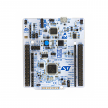
The signal for the DAC comes from an ST NUCLEO-L433RC-P development board. The audio is a WAV file stored in 12-bit 44kHz format. The WAV file is stored in external flash and the MCU reads the WAV file using SPI with DMA, this is then sent to the DAC using DMA.

The 3.3V used to generate the 1.65V op-amp bias also comes from this development board, via a header pin.

https://www.st.com/en/evaluation-tools/nucleo-l433rc-p.html

1750426248996.png
When I reset the software on the ST dev board (by running in debug mode using STM32 CubeIDE), this is the noise heard from the speaker...

https://www.dropbox.com/scl/fi/a082...udio.m4a?rlkey=6xixv119b12ubf8fxkq9zwcdu&dl=0

When I start the software on the ST dev board, it repeats the voice prompt "seven" and sound like this...

https://www.dropbox.com/scl/fi/hypw...udio.m4a?rlkey=ff4u2mhsuo21u0y50j760rad3&dl=0

You can hear all sorts of hummming and clicking, it can only be coming from the source as there is only a slight hiss when the input to the PAM8302A is floating or grounded. I dont know how to resolve the issue and at a loss.
 
Last edited:

Thread Starter

freeflyer

Joined Sep 9, 2016
169
hi ff,
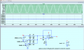
For demo only.
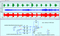
Your circuit with a Voice countdown on one channel input, and music [Fly2]
on the combined L/R audio input.

The Out plot is what the use would hear

E
Delete the .txt extension on the wav files if you want to play them.
View attachment 351518
Many thanks for all your effort Eric, this is exactly the result I am looking for.

My circuit is the same as your simulation, apart from the op-amp is a TLV2372 and the feedback resistor is 22k.

I tried 44k, but that gain was too high causing the audio to be loud and distorted.

If only the real audio on my setup sounded like that !

If you refer to my previous post, I have recorded the poor audio quality with links so you can hear for yourself.
 

ericgibbs

Joined Jan 29, 2010
21,477
hi ff,
I played the audio files on that webpage [ I don't want to log in], but I can see why the voice signal is distorted, the DAC signal is based on the Zero line.

Any chance you could post a wav file of the DAC signal to this thread?

E
 

ci139

Joined Jul 11, 2016
2,006
could try replacing the one on the dev board
i wouldn't rush messing with dev board (just incase it's still authentic . . . and the source of the problem is largely unidentified) =
= ? if it works at 5V --or-- you have no feedback capacitor at LM4871 gain chain --or-- your Li-Ion has a current limitter or otherwise poor discharge characteristics

incase you feed in too high sig. level --or-- overamplify it at LM4871
https://www.google.com/search?q=LM4871+capability+thermal+protection+test
 
Last edited:

ericgibbs

Joined Jan 29, 2010
21,477
hi ff,
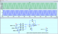
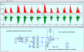
As a quick demo I have referenced my audio voice countdown signal to 0V as per the DAC out., listen to out9.wav, is that what you hear on your project??
E
EG 1548.png
 

Attachments

Thread Starter

freeflyer

Joined Sep 9, 2016
169
hi ff,
As a quick demo I have referenced my audio voice countdown signal to 0V as per the DAC out., listen to out9.wav, is that what you hear on your project??
E
View attachment 351533
The WAV file is attached, but you need to be aware it has been converted from 16-bit signed 44Khz to 12-bit unsigned 44kHz. This is because the DAC on the ST MCU is only 12-bit. The WAV header has also been removed (first 44 bytes). So it will not play as a standard WAV file.

The python script to convert 16-bit signed 44Khz to 12-bit unsigned 44kHz is also attached for reference (wav_to_12bit.py).

Regarding the out9.wav you attached, this is not the case with my setup.

The noise you hear in the first link is with no WAV playing, the MCU is halted at the start of the progran so the DAC is not playing. But you can hear the hum where there should be silence.

The second link shows the voice prompt audio being played but with hum and noise in the background.

I've tried two different speakers inserted into my helmet, but the bluettooth music sounds tinny and is uncomfortable in your ear as it feels too loud but poor quality. Its fine for voice prompts, but I dont think I am going to be able to find a solution to play bluetooth music.

It needs a much better quality amp and speaker setup which is very difficult to achieve in such a small package. So I might have to for go the bluetooth music and just use the voice prompts, but that was a feature I really wanted so Im now not sure if I will continue with this project, unless I can find a suitable speaker and amp in a small package thats decent quality.
 

Attachments

MisterBill2

Joined Jan 23, 2018
27,722
hi ff,
The TLV has no gain, just a buffer???
E
LOOK AT THE CIRCUIT in post #59!! Certainly it has NO GAIN!! Not "unity gain, but NO GAIN! The voltage gain of the inverting input configuration G= Rf/ Rin. In this case Rf=0 In addition to that, the output impedance of an opamp is always very low, in theory it is ZERO. For unity gain the TS must have a feedback resistor between the output and the inverting input.
 
Last edited:
Top