Facebook
 Google
 GitHub
 Linkedin

Hi all,
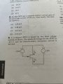
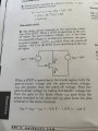
Studying for the FE Exam and I have found the "FE Electrical and Computer Practice Problems" study guide by Michael Lindeburg very helpful thus far. I am near the end, and this is the first problem I am a bit stuck on the solution and just want to make sure I am not misunderstanding, as these darn semiconductor circuits have been one of my weaker areas.
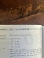
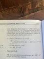
I have posted the full problem and solution for problem 9.
My hang up is on how they find the gate-to-drain voltage. I am fine up to VGD = VGS - VDS, but I also know VGS = VG - VS and VDS = VD - VS. VS is connected to the positive terminals of both sources. That to me seems to imply VGS would be 2V and VDS -1.9V, but the solution has that flipped and ends up with VGD = -3.9V. Could somebody help explain if the solution is correct, what I am overlooking.
Thanks!
Studying for the FE Exam and I have found the "FE Electrical and Computer Practice Problems" study guide by Michael Lindeburg very helpful thus far. I am near the end, and this is the first problem I am a bit stuck on the solution and just want to make sure I am not misunderstanding, as these darn semiconductor circuits have been one of my weaker areas.
I have posted the full problem and solution for problem 9.
My hang up is on how they find the gate-to-drain voltage. I am fine up to VGD = VGS - VDS, but I also know VGS = VG - VS and VDS = VD - VS. VS is connected to the positive terminals of both sources. That to me seems to imply VGS would be 2V and VDS -1.9V, but the solution has that flipped and ends up with VGD = -3.9V. Could somebody help explain if the solution is correct, what I am overlooking.
Thanks!
Attachments
-
 73.3 KB Views: 15
-
 94.3 KB Views: 13
-
 68.5 KB Views: 10
-
 78.4 KB Views: 10