Same digital signal from different output doesn't give the same result

Thread Starter

Scuud52

Joined Nov 29, 2018
3
Hello

i'm working on a prototype using an Arduino and a light sensor. The two communicates using UART.

when i'm using a FTDI device to send a message to the sensor, it reacts accordingly, but when i'm using the Arduino it doesn't do anything, as if it just doesn't receive the message.

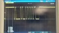
i used an oscilloscope to be able to understand what's happenning. I took the signal from the closest I could from the sensor.

I linked the oscillograms (on the arduino signal, the time cursors are in the wrong position, but the lenght of the signal is the same on both cases)

I also plugged the Arduino Serial output to the FTDI to see how the Arduino signal is received. it looks fine appart from some mild glitches sometimes.

I really don't understand why the signal gets lost somewhere. Could it be because of the shape that is slightly different, could it be the bitrate that is not exactly the same even if i set it to be the same (like if the clock is slightly off, a 115200 bit rate is in fact 115100)

Thanks a lot
 

Attachments

sc0tch

Joined Nov 6, 2018
64
What does the data sheet for the light sensor say. As far as gate threshold voltages, baud rate, etc.

Voltage for logic high is 0.2 Volts higher on the FTDI readings. Also post your schematic with any pullup or pull down resistors your using.
 

Thread Starter

Scuud52

Joined Nov 29, 2018
3
The datasheet doesn't provide much info about the UART link.

it just says 115200 bauds.

The sensor datasheet (here) just provide this information (attached)

Vdd in my case is 5V, but the arduino originaly is a 5V Uart signal and it still doesn't work.

I didn't use any Pull Up or pull down, so basically my circuit is just the output of the FTDi or the ADRUINO going straight into the Sensor's pins.

I cannot be sure if the FTDI uses pull up resistor but the Arduino doesn't. I tried to put a PU or PD resistor but it doesn't give any different results.

Thanks
 

Attachments

sc0tch

Joined Nov 6, 2018
64
The datasheet doesn't provide much info about the UART link.

it just says 115200 bauds.

The sensor datasheet (here) just provide this information (attached)

Vdd in my case is 5V, but the arduino originaly is a 5V Uart signal and it still doesn't work.

I didn't use any Pull Up or pull down, so basically my circuit is just the output of the FTDi or the ADRUINO going straight into the Sensor's pins.

I cannot be sure if the FTDI uses pull up resistor but the Arduino doesn't. I tried to put a PU or PD resistor but it doesn't give any different results.

Thanks
According to the datasheet vdd typical voltage is 3.3V with a Max of 3.5V and input voltage logic high is VDD+/- 0.3v so logic high threshold . Your oscilioscope reading shows 2.97V which I'd imagine should be high enough but could be wrong, but then again no guranteed that VDD isn't 3.4v or 3.5v either. Rise and fall times are also not as clean/fast on the Arduino so it's also possible that there is some issues in the transient threshold range between logic high and logic low.
Screenshot_20181206-125737.png Screenshot_20181206-125724.png
 

ebp

Joined Feb 8, 2018
2,332
It really is very difficult to compare the signals given the difference in the way the photos were made. it appears that the rise and fall of the signals from the FTDI are faster. It looks like there is large overshoot (negative going spikes) on the falling edges with the FTDI part, but this may be an artifact due to inappropriate probing technique. The transitions from the Arduino look too slow to me, like there is significant capacitive loading, as perhaps from a long cable. The transitions aren't slow enough to cause problems with any reasonable receiver, but if the data is being received by an ordinary digital input with no hysteresis there might be problems.
It would be helpful to use the cursors to accurately measure the character times or bit times.

In asynchronous communication baud rate needs to match reasonably well but not perfectly. Typically everything is likely to work if the rate is off by no more than about 1/4 of a bit time over the full period of a character, so for 10 bits (start, 8 data, stop) that is about 1/40 of a character time or 2.5%. In reality, the error can often be somewhat larger. It does depend on the sampling algorithm used, primarily the accuracy of detection of the leading edge of the START bit.
 

sc0tch

Joined Nov 6, 2018
64
My best guess though is the rise of the Arduino however. It's really slow in that last half volt of it's rise and is probably causing issues with the sensor especially as it's really not even reaching the technical spec of logic high for the sensor.

I'm sure somebody more knowledgeable than me will have some good solutions for cleaning up the square wave but you can try something such as a high speed comparator to set a lower threshold voltage and send it's output to the sensor, but I'm certainly not an expert in this area
 

ebp

Joined Feb 8, 2018
2,332
"... and input voltage logic high is VDD+/- 0.3v so logic high threshold ..."

Huh? You are looking at the absolute maximum allowable voltages, which have nothing to do with required logic levels, only the limits beyond which they must not go without current limiting. The logic HIGH spec is 0.7 x VDD minimum and the LOW spec is 0.3 x VDD maximum. see page 11 of the datasheet.

=====
From the datasheet:
"The UART block implements the TX and RX signals as defined in the RS-232 ..."
This is complete nonsense. RS-232 does not define the data format but it does define voltage levels and they most certainly are not 0 to 3 volts. To be RS-232 compliant, the data line must be between -3 V and -15 V for "MARK" and between +3 V and +15 V for "SPACE." The line idles in the MARK condition and a start bit is a SPACE.
 

sc0tch

Joined Nov 6, 2018
64
"... and input voltage logic high is VDD+/- 0.3v so logic high threshold ..."

Huh? You are looking at the absolute maximum allowable voltages, which have nothing to do with required logic levels, only the limits beyond which they must not go without current limiting. The logic HIGH spec is 0.7 x VDD minimum and the LOW spec is 0.3 x VDD maximum. see page 11 of the datasheet.

=====
From the datasheet:
"The UART block implements the TX and RX signals as defined in the RS-232 ..."
This is complete nonsense. RS-232 does not define the data format but it does define voltage levels and they most certainly are not 0 to 3 volts. To be RS-232 compliant, the data line must be between -3 V and -15 V for "MARK" and between +3 V and +15 V for "SPACE." The line idles in the MARK condition and a start bit is a SPACE.
Thanks for the clarification there ebp.

Correct me if I'm wrong, but that gives logic high if about 2.45V which the Arduino seems to have slow rise time as it comes above roughly 2V so could still he slow rise time of the Arduino there?
 
Last edited:

Thread Starter

Scuud52

Joined Nov 29, 2018
3
Thanks for your answer.

It would be annoying to add any part to the circuit in order to make it work because it's just a prototype meant to be used as a proof of concept, the Arduino will not be used in the final product.

Anyway I tryed to not use a voltage divier out of the Arduino, still no results.

I also tryed to power the device with 3.3V instead of 5V, no result still.

I guess i'll have to find another way to prove the concept, but it really bugs me!
I guess so far, we can assume that the shape of the Arduino Signal explain why it doesn,t work, althought I'm nto satisfied with this explanation

Thanks for your answer, hopefully somebody will know more and come up with an explanation
 
Top