Multi-Device Communication on same bus

Thread Starter

Embededd

Joined Jun 4, 2025
152
Hi, I want to confirm my understanding regarding UART communication.

If one MCU UART TX line is connected to multiple device RX lines, then all devices can receive the same transmitted data because RX pins are only inputs.

But if one MCU UART RX line is connected to multiple device TX lines, then communication is safe only when a single device transmits at a time. If multiple TX lines transmit simultaneously, bus contention/collision can occur because UART does not provide arbitration like I2C.

Is my understanding correct?
 

MrChips

Joined Oct 2, 2009
34,767
Hi, I want to confirm my understanding regarding UART communication.

If one MCU UART TX line is connected to multiple device RX lines, then all devices can receive the same transmitted data because RX pins are only inputs.

But if one MCU UART RX line is connected to multiple device TX lines, then communication is safe only when a single device transmits at a time. If multiple TX lines transmit simultaneously, bus contention/collision can occur because UART does not provide arbitration like I2C.

Is my understanding correct?

That is not the problem.
You cannot connect multiple TX lines together unless the TX drivers are designed for "party line" communications.

This is true for all digital logic gates. You cannot connect the outputs of gates together unless they have "open collector" or "open drain" outputs.

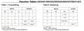
Wired AND.jpg

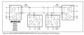
If you want to create a local area network, use RS-485 transceivers.
 

Irving

Joined Jan 30, 2016
5,107
But if one MCU UART RX line is connected to multiple device TX lines, then communication is safe only when a single device transmits at a time. If multiple TX lines transmit simultaneously, bus contention/collision can occur because UART does not provide arbitration like I2C
True for some UARTs but RS485 (and other protocols) signalling provide for this, with extended start bit and/or monitoring their transmission preamble for corruption using their own RX side.
 

MrChips

Joined Oct 2, 2009
34,767
But if one MCU UART RX line is connected to multiple device TX lines, then communication is safe only when a single device transmits at a time. If multiple TX lines transmit simultaneously, bus contention/collision can occur because UART does not provide arbitration like I2C.
With master-slave networks, the master has control of the bus. A slave device is allowed to transmit only when requested to do so. No two slaves can transmit at the same time.

With peer-to-peer communications, two devices can transmit at the same time. CDMA (collision detection/multtple access) protocol is designed to detect collisions and to arbitrate which device is given priority,
 

Ian0

Joined Aug 7, 2020
13,126
What would happen if you hard-wire 3 different audio outputs to the same loudspeaker (excluding the likely explosion)? :D
It would likely damage the outputs of at least one of the amplifiers, and the speaker would be OK. Pretty good analogy!
 

meth

Joined May 21, 2016
303
Sorry for my stupid joke. My point was, even not knowing all possible comm protocols, purely by logic, if 3 devices send digital signals at the same time, on the same line, without any phase/frequency encoding, with same baud rate and voltage level , what would you expect to happen?

I always encourage my colleagues to ask anything, but the answer to this one seems to obvious.
 

MrChips

Joined Oct 2, 2009
34,767
You don't have to resort to analogies. Just teach the real thing.

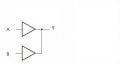
What happens when the outputs of two digital gates are connected?

Wired Outputs.jpg


What is the output Y when A is LO and B is HI?

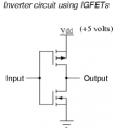
Here is a simplification of a CMOS inverter.


1778245764003.png

When the outputs of two gates are fighting against each other, one output is trying to pull the junction high while the other output is trying to pull the junction low. This creates a short circuit across the power rails. A high current flows and the gates are destroyed (unless the current is limited).
 

MrChips

Joined Oct 2, 2009
34,767
There are three types of outputs with digital gates, (i) totem-pole, (ii) open collector or open drain, and (iii) tri-state.

(i) totem pole: the output circuit shown in the previous post is an example of a CMOS totem-pole output. As explained, you cannot connect totem-pole outputs together.

(ii) open collector refers to a BJT output where the collector of the BJT is not connected. Open drain is a FET output configuration where the drain is not connected. These types of outputs can be directly wired together to create what is called wired-AND for positive logic and wired-OR for negative logic. In both cases, a LOW voltage output takes priority. A HIGH voltage output is presented via an external pull-up resistor only when all outputs are logic HI. This is called a "party-line" interface. Any party can pull the line LO. This is why it is called wired-OR when using negative logic. Any active-LOW signal wins.

(iii) tri-state: so named because there is a third state besides logic LO and HI. That third state is when the output is neither LO nor HI. The third state is a high-impedance state. RS-485 transceivers can be disabled to present a high impedance state.
 

John P

Joined Oct 14, 2008
2,059
In an RS485 system, you have to set up some kind of protocol to decide which node is going to transmit, because only one can do it at a time (as has been mentioned here). Most commonly, that's a master-slave arrangement where one particular unit explicitly addresses the others, one at a time. Another way to do it is with a token-passing scheme, where the nodes are somehow successively authorized to transmit. It's pretty complicated--how does the token get recognized, what happens if one unit never lets go of it, how can the token be regenerated if it gets lost--all a lot to handle for a small processor.

Or there's CAN bus, where an external communication processing device takes care of bus contention, and the individual processors just send out messages, and the interface chip hands over complete incoming messages, maybe filtered so undesired messages are rejected. Some PIC processors have this function built-in, so the external chip isn't needed. The CAN protocol is complicated, but the user never needs to understand how the magic works!
 

Ian0

Joined Aug 7, 2020
13,126
The CAN protocol is complicated, but the user never needs to understand how the magic works!
That's the main thing about CAN. It's a pain to get it set up and running, but when you've got through that, the hardware takes care of everything. Unlike RS485 where there is always a software overhead.
 

meth

Joined May 21, 2016
303
I think the TS is not referring to a polling protocol, he is interested in multiple devices sending data on the same line at the same time.

You can see from Mr. Chips' post how much conflict is there resolving a single state. Now multiply that for at least 9600 times per second..
 
That’s a fair point. If the requirement is just multiple devices sharing one line, adding more GPIOs can feel like avoiding the actual bus arbitration problem. At that point, using proper addressing, tri state outputs, or a protocol designed for multi drop communication usually scales better than multiplying pins.
 
Top