Sallen key butterworth bandpass filter

Thread Starter

nicole

Joined Apr 29, 2013
6
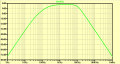
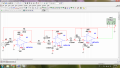
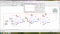
Hi all, i have designed a butterworth bandpass filter that passes frequencies between 100Hz to 10kHz and with gain of 2 using LM741. But the bode plot of the simulation result seems incorrect. Can anyone help? Thank you.
 

Attachments

Last edited:

Thread Starter

nicole

Joined Apr 29, 2013
6
Here you have a "body plot" that I got from LTspice.
Thanks for the reply. I am using NI multisim in designing my filter. Yet i unable to get the bode plot as shown in your figure. Do u know anything wrong with my circuit? I am combining a highpass and a low pass filter in designing my bandpass filter.
 

Papabravo

Joined Feb 24, 2006
21,225
The crappy and obsolete 741 opamp maxes out at about 9 kHz. It has no capability to do much of anything. Abandon it in favor of a part that was designed in the last decade instead of the last century.
 

Thread Starter

nicole

Joined Apr 29, 2013
6
The crappy and obsolete 741 opamp maxes out at about 9 kHz. It has no capability to do much of anything. Abandon it in favor of a part that was designed in the last decade instead of the last century.
But the problem is the questions request me to design the filter using LM741. So can't abandon it.
 

Papabravo

Joined Feb 24, 2006
21,225
But the problem is the questions request me to design the filter using LM741. So can't abandon it.
Then you need to change instructors because he is an idiot for giving such an assignment. Using an LM741 you have no idea weather the response is limited by the opamp or the frequency determining components. Can you say for sure how the rolloff is affected by those things? It is extremely poor design practice to use a device so close to its limits. If you worked for me and proposed such a thing I'd have to think seriously about firing you. No joke Sherlock, I don't have time to waste on boneheaded ideas from instructors who are decades behing the times.
 
Top