[S.T. 4 ] - Capacitive and Inductive filtered rectifiers

Thread Starter

PsySc0rpi0n

Joined Mar 4, 2014
1,755
My next task is to analyse this kind of circuits...

First question is:

Is it possible to measure the minimum value of v_out waveform using ".meas" command?

I know how to do it for MAX values:

Code:
.meas v_out MAX V(out)
And what about for minimum value?

Edited;
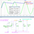
What I need is to measure MAX value and MIN value of a rectified waveform and check the V ripple. With these values I could easily find V ripple!
 
Last edited:

Thread Starter

PsySc0rpi0n

Joined Mar 4, 2014
1,755
hi,
After you have run the sim, use Menu View/Spice Error log to see your measure results.
I know about error log to see measures but v_ripple_min cannot be zero, right? That's why I think "MIN" directive is not being processed by LTSpice as "MAX" is!

But the values that I have in the screen attached are with cursors manually positioned in the plot. So, that might be not as accurate as measure command would be!
 

Attachments

Last edited:

Thread Starter

PsySc0rpi0n

Joined Mar 4, 2014
1,755
Ok, I got it...

Now I need to know how to calculate the cap value so that Vripple is about 0% of it's max value...

As far I as understand, Vripple our teacher wants is:

Vripple.gif

Now how do I calculate C, so that Vripple = 0.684V???
 

ericgibbs

Joined Jan 29, 2010
18,766
You could use the formula Q = C *V, where Q= I * t, this assumes a linear discharge from Vmax to Vmin.

So work out the average current over the period between Vmax and Vmin and use the above formula.
Post what you the think the Cap value is and to confirm that it is close enough change the Cap value in the Sim and re-run the sim.

Extend the .tran period to get a more accurate value for I_load and Vmax/min, say 200mS
 
Last edited:

Thread Starter

PsySc0rpi0n

Joined Mar 4, 2014
1,755
Well, I did it like this:

I_load.gif

Then:

cap_value.gif

But when I change the cap value to 343.7uF, the vripple is about 1.12V and not 0.684V as previously calculated! What is wrong?
 

Thread Starter

PsySc0rpi0n

Joined Mar 4, 2014
1,755
The Iavg is close enough, but where did you get that second formula.?

Retry using C= [I * t]/Vrip, where t is ~ 1/5o
2nd formula is here in Vripple section
http://www.zen22142.zen.co.uk/Design/dcpsu.htm

and this link was taken from some thread from AAC that google returned to me!

Ok, let me try using that formula!


Edited;
Ok, that formula gives me correct results, but what's wrong with the other one?


Edited2;

Ok, I think that the formula I used is specific for full-wave rectifiers... I'm using half-wave rectifier, so that "2" in the formula I used was messing my calcs up!

Please, confirm this with me, Mr. EricGibbs!

Close enough is perfect, as your signature says!
 
Last edited:

Thread Starter

PsySc0rpi0n

Joined Mar 4, 2014
1,755
I use this formula for Vripple Cap value.

Time = (R * C) * ln(Vmin/Vmax)

Transpose for Cap and compare the result from your corrected formula, lets see how they compare.:)

In practice most high value electrolytic caps have a tolerance values of +/-20% or higher.!
http://www.electronics-tutorials.ws/capacitor/cap_3.html

In is the current across the load resistor?
Vmin and Vmax are the V outs as if the circuit has no capacitor????
And Time is what??? Time between peaks???
 

ericgibbs

Joined Jan 29, 2010
18,766
Its not In its Ln [ natural logarithm]:)

Vmax and Vmin are the smoothed voltage on the capacitor, example Vmax = 7.7V and Vmin = 7V , Natural Log, Ln(7/7.7)
Vripple = Vmax -Vmin

If you recall from a previous question, for a 50Hz frequency the Period is 20mSec, but using a half wave rectifier the forward conduction period is 'ideally' only 10mSec, but due to the Vfwd of the diode this is reduced.

The other factor to consider is the 're-charging' period of the capacitor, during this time the positive cycle is supplying current to recharge the capacitor and the load [330R]. Using LTS to measure this gives ~ 2.4mS recharge time.

If you now measure from the Vmax to the Vmin of the plot you will see that the actual capacitor discharge time is ~17.7mSec, this the time for the equation.

Note the SUM of recharge time and discharge times is 20mSec
 

Thread Starter

PsySc0rpi0n

Joined Mar 4, 2014
1,755
Apart of all those details, I'm just looking for an approximate value for the capacitor that gives me a ripple of 10% of it's max value!!! I think I got that using the above formulas you suggested. But If I use a full wave rectifier, the formula for C is a bit different. It has the f_out difference which is double. In my case is 20mS. In full-wave is 10mS...

Note:

20mS period are 50Hz, right?
Doubling that period, I'll get 10mS, right?

So, how many Hertz is an half period of 20mS???

If 20mS are 50Hz
Then 10mS are x
x = (50*10)/20 = 25Hz...
Not good. Should be 100Hz...

Where the hell am I going wrong here??? I'm going mad!
 

ericgibbs

Joined Jan 29, 2010
18,766
hi Psy,
As you know, the Period of a Sine wave is the inverse of the Frequency, ie: 1/50 = 0.02Secs

With a single diode rectifier driven by a 50Hz voltage source, only conducts on the positive half cycle, so the Period between capacitor charging pulses is 20mSec. [10mSec forward biased, 10mSec reverse biased]

With a bridge/dual diode rectifier the diode/s conduct on both half cycles of the input Sine wave, so the Period between the capacitor charging pulses is 10mSec.

You are not going mad.. you are over thinking the problem.;)

Eric

EDIT:
This image may help.
Half wave and Full wave rectification.
I have used a 600uF cap on both circuits.
 

Attachments

Last edited:

Thread Starter

PsySc0rpi0n

Joined Mar 4, 2014
1,755
hi Psy,
As you know, the Period of a Sine wave is the inverse of the Frequency, ie: 1/50 = 0.02Secs

With a single diode rectifier driven by a 50Hz voltage source, only conducts on the positive half cycle, so the Period between capacitor charging pulses is 20mSec. [10mSec forward biased, 10mSec reverse biased]

With a bridge/dual diode rectifier the diode/s conduct on both half cycles of the input Sine wave, so the Period between the capacitor charging pulses is 10mSec.

You are not going mad.. you are over thinking the problem.;)

Eric

EDIT:
This image may help.
Half wave and Full wave rectification.
I have used a 600uF cap on both circuits.

I understand the theory which makes all sense... What I'm not understanding and what is leaving me mad is the math I did in the previous post...

I should get 100Hz for 10mS but I'm getting 25Hz instead!
 

ericgibbs

Joined Jan 29, 2010
18,766
Period= 1/Frequency

Per1 = 1/100 = 0.01 Sec
Per2 = 1/25 = 0.04 Sec

So, how many Hertz is an half period of 20mS???' Half of 20mS is 10mS, which is only one half cycle.
If 20mS are 50Hz
Then 10mS are x
x = (50*10)/20 = 25Hz... ' x= (50 * 0.02)/0.01 =100 HALF cycles
Not good. Should be 100Hz...
 

ericgibbs

Joined Jan 29, 2010
18,766
Why you say it's (50*0.02)/0.01???
Because a 50Hz sine wave has a Period of 20mSec, in 1 second there will be 50 periods of 20mSec.

So there must be 100 periods of 10mSec in 1 second

is incorrect.!
You are confusing complete cycles of a 50Hz SINE wave, with a Period of 20mSec with 100 rectified half cycles of 10mSec
 
Last edited:
Top