
 Facebook
 Google
 GitHub
 Linkedin
Please check if my plan will work, or what you would change so I can avoid horrible fire in moms basement.
Parts:
(1) Raspberry Pi 0 W
https://www.amazon.com/Raspberry-Pi...52111509&s=gateway&sprefix=ras,aps,152&sr=8-6
(2) 5v 500mA Solar Panels
https://www.amazon.com/gp/product/B00CBT8A14/ref=ppx_yo_dt_b_asin_title_o02_s00?ie=UTF8&psc=1
(1) RC car with 3.7v 400mAh Lithium Iorechargeablele battery pack.
https://www.amazon.com/gp/product/B07CLPLYHP/ref=ppx_yo_dt_b_asin_title_o01_s00?ie=UTF8&psc=1
(1) 5v DC-DC Buck Converter fixed 5v output.
https://www.amazon.com/Regulator-DR...=gateway&sr=8-1-spons&psc=1&smid=AFHAE9RJVUMB
(1) L293D DC Motor Driver - runs two motors, forward/back and left/right
https://www.amazon.com/PIXNOR-16-pi...keywords=L293&qid=1552105249&s=gateway&sr=8-1
***** HELP HERE *****
(1) TP4056 Charging Module 5V - I am not sure this is ok to use for my 3.7 Li-on battery?
https://www.amazon.com/Makerfocus-C...s=TP4056&qid=1552108464&s=gateway&sr=8-2&th=1
***** HELP HERE *****
(1) Transistor? Mosfett? Something so I can turn on and off solar panel power to charging the unit while in operation. I don't know what to use here.
***** HELP HERE *****
(1) Schottky diode? Something to prevent back flow to solar panel from battery pack?
--------------------------------------------------------------------------------------------------------------------------------------------------------------------------------------
T H E M A S T E R P L A N
---------------------------------------------------------------------------------------------------------------------------------------------------------------------------------------
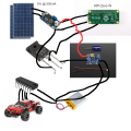
I am using two 5v 500mA Solar Panels in series to generate an approximate 10v @ 500mA. This Solar Array connects to my 5v DC-DC Buck converter which turns the power into a fairly clean 5v. I attached that 5 volts to my Raspberry Pi zero W which idles around 5v 130mA.
Next, I will connect the L293D motor driver up to the Pi and the cars 3.7v Battery pack, so when the Pi tells the L293D to power the motor, the L293D chip uses the 3.7v Battery for power.
Next step, punch myself in face because here is where it gets way to hard.
1) The Pi will disable the solar panel from charging the car's 3.7v battery to avoid overdrawing power and shutting off the Pi.
** Problem 1 **
I think this is done through a transistor, but which type? I imagine there is a wire coming from the 5v Buck converter into a transistor that connects to the TP4056 Charging Module and then to the battery and the other transistor wire to a pin on the Pi. When the Pi pin turns on, I want the transistor to stop letting power pass between my buck converter and the charger. Also the transistors I saw allow 1A of current, but I probably shouldn't allow more than 400mA for battery charging as 1A would cut voltage and possibly shut down the Pi.
2) Next, the Pi will tell the L293D chip to engage one or two of the motors, and the L293D will automatically use power from the 3.7v battery as that is the connected power source.
3) After the driving maneuver is complete, the Pi will re-engage the power from the buck converter to the charging IC so the battery can recharge.
** Problem 2 **
If all that looks doable, the only other question I have is, should I put a Schottky diode between the buck converter and the charging module? If so what kind / size?
Thanks for your help, I know it's a long read. Let me know if you need me to give more information.
I don't know how to make a real schematic of this for you, so some imagination is required.
Parts:
(1) Raspberry Pi 0 W
https://www.amazon.com/Raspberry-Pi...52111509&s=gateway&sprefix=ras,aps,152&sr=8-6
(2) 5v 500mA Solar Panels
https://www.amazon.com/gp/product/B00CBT8A14/ref=ppx_yo_dt_b_asin_title_o02_s00?ie=UTF8&psc=1
(1) RC car with 3.7v 400mAh Lithium Iorechargeablele battery pack.
https://www.amazon.com/gp/product/B07CLPLYHP/ref=ppx_yo_dt_b_asin_title_o01_s00?ie=UTF8&psc=1
(1) 5v DC-DC Buck Converter fixed 5v output.
https://www.amazon.com/Regulator-DR...=gateway&sr=8-1-spons&psc=1&smid=AFHAE9RJVUMB
(1) L293D DC Motor Driver - runs two motors, forward/back and left/right
https://www.amazon.com/PIXNOR-16-pi...keywords=L293&qid=1552105249&s=gateway&sr=8-1
***** HELP HERE *****
(1) TP4056 Charging Module 5V - I am not sure this is ok to use for my 3.7 Li-on battery?
https://www.amazon.com/Makerfocus-C...s=TP4056&qid=1552108464&s=gateway&sr=8-2&th=1
***** HELP HERE *****
(1) Transistor? Mosfett? Something so I can turn on and off solar panel power to charging the unit while in operation. I don't know what to use here.
***** HELP HERE *****
(1) Schottky diode? Something to prevent back flow to solar panel from battery pack?
--------------------------------------------------------------------------------------------------------------------------------------------------------------------------------------
T H E M A S T E R P L A N
---------------------------------------------------------------------------------------------------------------------------------------------------------------------------------------
I am using two 5v 500mA Solar Panels in series to generate an approximate 10v @ 500mA. This Solar Array connects to my 5v DC-DC Buck converter which turns the power into a fairly clean 5v. I attached that 5 volts to my Raspberry Pi zero W which idles around 5v 130mA.
Next, I will connect the L293D motor driver up to the Pi and the cars 3.7v Battery pack, so when the Pi tells the L293D to power the motor, the L293D chip uses the 3.7v Battery for power.
Next step, punch myself in face because here is where it gets way to hard.
1) The Pi will disable the solar panel from charging the car's 3.7v battery to avoid overdrawing power and shutting off the Pi.
** Problem 1 **
I think this is done through a transistor, but which type? I imagine there is a wire coming from the 5v Buck converter into a transistor that connects to the TP4056 Charging Module and then to the battery and the other transistor wire to a pin on the Pi. When the Pi pin turns on, I want the transistor to stop letting power pass between my buck converter and the charger. Also the transistors I saw allow 1A of current, but I probably shouldn't allow more than 400mA for battery charging as 1A would cut voltage and possibly shut down the Pi.
2) Next, the Pi will tell the L293D chip to engage one or two of the motors, and the L293D will automatically use power from the 3.7v battery as that is the connected power source.
3) After the driving maneuver is complete, the Pi will re-engage the power from the buck converter to the charging IC so the battery can recharge.
** Problem 2 **
If all that looks doable, the only other question I have is, should I put a Schottky diode between the buck converter and the charging module? If so what kind / size?
Thanks for your help, I know it's a long read. Let me know if you need me to give more information.
I don't know how to make a real schematic of this for you, so some imagination is required.





